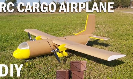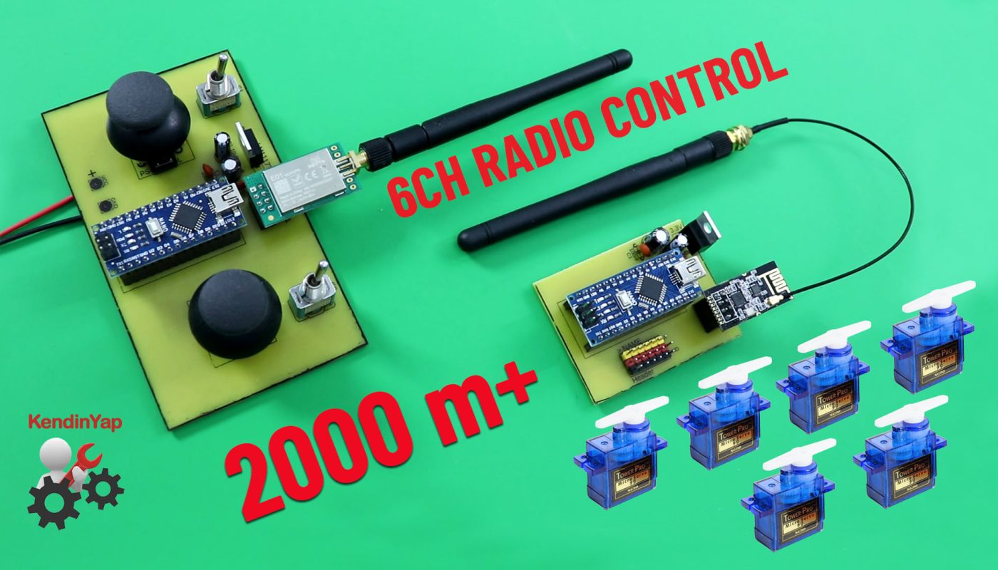
Arduino ve 2.4Ghz NRF24L01 Modülleri ile 6 kanallı, uzun menzilli uzaktan kumanda yapımı.
6 Kanallı bu uzaktan kumanda devresi ile RC uçak, RC araba, RC tekne, RC iş makinaları, RC tank gibi model araçları kontrol edebilirsiniz.
İdeal koşullar altında uzaktan kumandanın maksimum menzili 2000 metrenin (1,24 mil+) üzerindedir.
Gerekli Malzemeler:
2 x PS4 Analogue Joystick (10K) : https://s.click.aliexpress.com/e/_DBSn2AB
2 x Toggle switch: https://s.click.aliexpress.com/e/_DCd5Pzh
1 x NRF24L01+PA+LN 100mW (E01-ML01DP5): https://s.click.aliexpress.com/e/_DmEoWQf
1 x NRF24L01+PA+Wireless SMD: https://s.click.aliexpress.com/e/_DekKUm9
2 x Arduino Nano: https://s.click.aliexpress.com/e/_DlhwLS3
2 x 100uF (16V or above) electrolytic kondansatör : https://s.click.aliexpress.com/e/_DBJpcn1
Dişi Header Pin (15 pins) 15P Female: https://s.click.aliexpress.com/e/_DDqmgbh
Universal PCB board: https://s.click.aliexpress.com/e/_DF8xNJ9
10uF electrolytic kondansatör : https://s.click.aliexpress.com/e/_DDVm071
100uF electrolytic kondansatör: https://s.click.aliexpress.com/e/_Ddfia2R
100nF (104) Seramik kondansatör: https://s.click.aliexpress.com/e/_DmUGp7T
LM1117 3.3 Regulator IC: https://s.click.aliexpress.com/e/_DEpLIel
2×4 pin Header: https://s.click.aliexpress.com/e/_DdnClhn
80W Havya: https://s.click.aliexpress.com/e/_DD75tWX
Dijital Multimetre AC DC A830L : https://s.click.aliexpress.com/e/_DmjzgOJ
Dijital Multimetre AC DC ANENG XL830L : https://s.click.aliexpress.com/e/_DEJiyIP
AA pil kutusu (5xAA pil) 5 Slot: https://s.click.aliexpress.com/e/_DFMnduf
Heat-Shrink (Makaron): https://s.click.aliexpress.com/e/_DnMQjEj
6 Kanal Versiyon GERBER ve PDF Dosyaları:
https://drive.google.com/file/d/1nzZ1APkTlRCIaTYjvVbUQuV6dDC1I2WS/view?usp=sharing
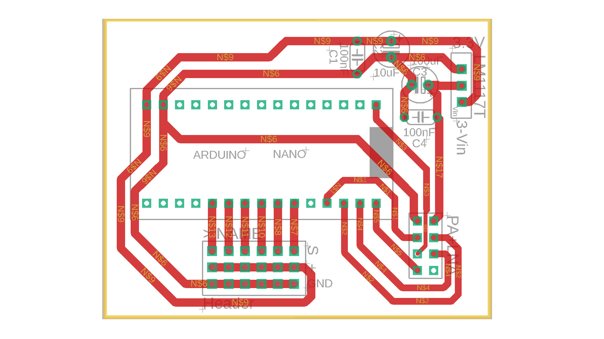
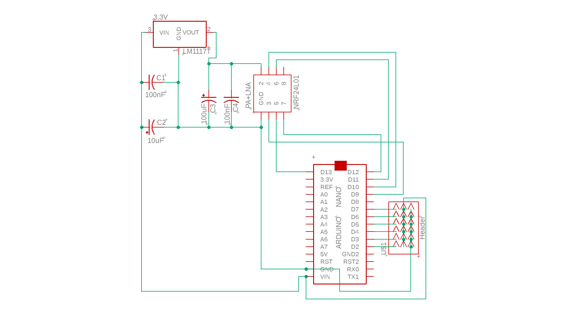
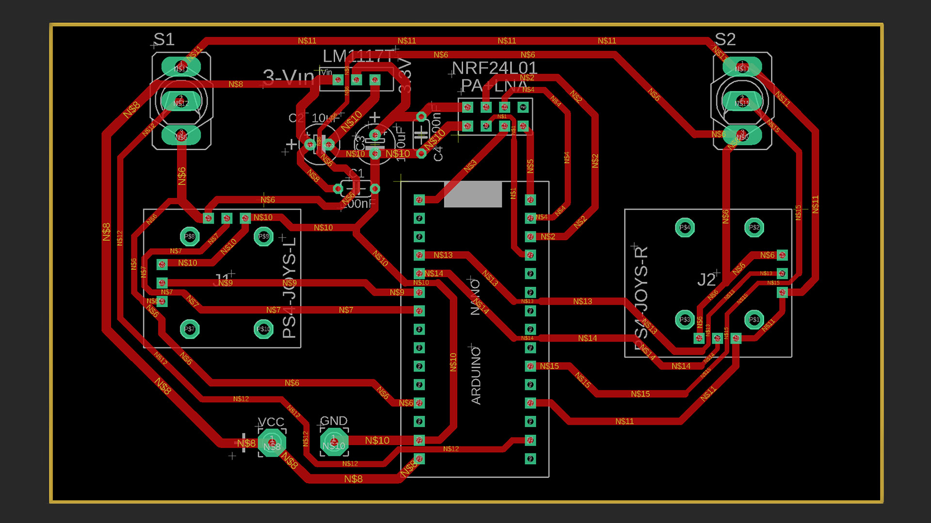
PCB Plaket ölçüleri:
Verici: 114 x 65mm
Alıcı: 60 x 45mm
Verici ve Alıcı Kodları (İndirme): https://drive.google.com/file/d/1nv7hXkNy-fmLANADhOJTKW3Nz5aKS14R/view?usp=sharing
6-Kanal Verici İçin Arduino Nano Kodu:
// 6 Channel Transmitter | 6 Kanal Verici
// KendinYap Channel

  #include <SPI.h>
  #include <nRF24L01.h>
  #include <RF24.h>
  const uint64_t pipeOut = 0xABCDABCD71LL;         // NOTE: The address in the Transmitter and Receiver code must be the same "0xABCDABCD71LL" | Verici ve Alıcı kodundaki adres aynı olmalıdır
  RF24 radio(9, 10);                               // select CE,CSN pin | CE ve CSN pinlerin seçimi

  struct Signal {
  byte throttle;
  byte pitch;
  byte roll;
  byte yaw;
  byte aux1;
  byte aux2;

};
  Signal data;
  void ResetData()
{
  data.throttle = 0;
  data.pitch = 127;
  data.roll = 127;
  data.yaw = 127;
  data.aux1 = 0;
  data.aux2 = 0;

}
  void setup()
{
                                       // Configure the NRF24 module  | NRF24 modül konfigürasyonu
  radio.begin();
  radio.openWritingPipe(pipeOut);
  radio.setChannel(100);
  radio.setAutoAck(false);
  radio.setDataRate(RF24_250KBPS);    // The lowest data rate value for more stable communication  | Daha kararlı iletişim için en düşük veri hızı.
  radio.setPALevel(RF24_PA_MAX);      // Output power is set for maximum range  |  Çıkış gücü maksimum menzil için ayarlanıyor.
  radio.stopListening();              // Start the radio comunication for Transmitter | Verici için sinyal iletişimini başlatır.
  ResetData();

}
                                      // Joystick center and its borders | Joystick merkez ve sınırları
  int Border_Map(int val, int lower, int middle, int upper, bool reverse)
{
  val = constrain(val, lower, upper);
  if ( val < middle )
  val = map(val, lower, middle, 0, 128);
  else
  val = map(val, middle, upper, 128, 255);
  return ( reverse ? 255 - val : val );
}
  void loop()
{

  data.roll = Border_Map( analogRead(A3), 0, 512, 1023, true );        // CH1   Note: "true" or "false" for signal direction | "true" veya "false" sinyal yönünü belirler
  data.pitch = Border_Map( analogRead(A0), 0, 512, 1023, true );       // CH2
  data.throttle = Border_Map( analogRead(A2),0, 340, 570, true );      // CH3   Note: For Single side ESC | Tek yönlü ESC için
  // data.throttle = Border_Map( analogRead(A2),0, 512, 1023, true );  // CH3   Note: For Bidirectional ESC | Çift yönlü ESC için
  data.yaw = Border_Map( analogRead(A1), 0, 512, 1023, false );        // CH4
  data.aux1 = digitalRead(0);                                          // CH5
  data.aux2 = digitalRead(3);                                          // CH6

  radio.write(&data, sizeof(Signal));
}
6-Kanal Alıcı İçin Arduino Nano Kodu:
//  6 Channel Receiver | 6 Kanal Alıcı
// KendinYap Channel

#include <SPI.h>
#include <nRF24L01.h>
#include <RF24.h>
#include <Servo.h>

int ch_width_1 = 0;
int ch_width_2 = 0;
int ch_width_3 = 0;
int ch_width_4 = 0;
int ch_width_5 = 0;
int ch_width_6 = 0;

Servo ch1;
Servo ch2;
Servo ch3;
Servo ch4;
Servo ch5;
Servo ch6;

struct Signal {

byte throttle;
byte pitch;
byte roll;
byte yaw;
byte aux1;
byte aux2;

};

Signal data;

const uint64_t pipeIn = 0xABCDABCD71LL;
RF24 radio(9, 10);

void ResetData()
{

data.throttle = 0;                                         // Define the inicial value of each data input. | Veri girişlerinin başlangıç değerleri
data.roll = 127;
data.pitch = 127;
data.yaw = 127;
data.aux1 = 0;
data.aux2 = 0;

}

void setup()
{
                                                           // Set the pins for each PWM signal | Her bir PWM sinyal için pinler belirleniyor.
  ch1.attach(2);
  ch2.attach(3);
  ch3.attach(4);
  ch4.attach(5);
  ch5.attach(6);
  ch6.attach(7);

  ResetData();                                             // Configure the NRF24 module  | NRF24 Modül konfigürasyonu
  radio.begin();
  radio.openReadingPipe(1,pipeIn);
  radio.setChannel(100);
  radio.setAutoAck(false);
  radio.setDataRate(RF24_250KBPS);                         // The lowest data rate value for more stable communication  | Daha kararlı iletişim için en düşük veri hızı.
  radio.setPALevel(RF24_PA_MAX);                           // Output power is set for maximum |  Çıkış gücü maksimum için ayarlanıyor.
  radio.startListening();                                  // Start the radio comunication for receiver | Alıcı için sinyal iletişimini başlatır.

}

unsigned long lastRecvTime = 0;

void recvData()
{
while ( radio.available() ) {
radio.read(&data, sizeof(Signal));
lastRecvTime = millis();                                    // Receive the data | Data alınıyor
}
}

void loop()
{
recvData();
unsigned long now = millis();
if ( now - lastRecvTime > 1000 ) {
ResetData();                                                // Signal lost.. Reset data | Sinyal kayıpsa data resetleniyor
}

ch_width_1 = map(data.roll, 0, 255, 1000, 2000);
ch_width_2 = map(data.pitch, 0, 255, 1000, 2000);
ch_width_3 = map(data.throttle, 0, 255, 1000, 2000);
ch_width_4 = map(data.yaw, 0, 255, 1000, 2000);
ch_width_5 = map(data.aux1, 0, 1, 1000, 2000);
ch_width_6 = map(data.aux2, 0, 1, 1000, 2000);

ch1.writeMicroseconds(ch_width_1);                          // Write the PWM signal | PWM sinyaller çıkışlara gönderiliyor
ch2.writeMicroseconds(ch_width_2);
ch3.writeMicroseconds(ch_width_3);
ch4.writeMicroseconds(ch_width_4);
ch5.writeMicroseconds(ch_width_5);
ch6.writeMicroseconds(ch_width_6);

}
__________________
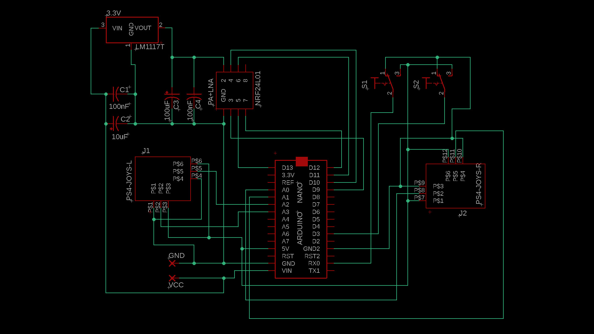
8 KANALLI VERSİYON
__________________
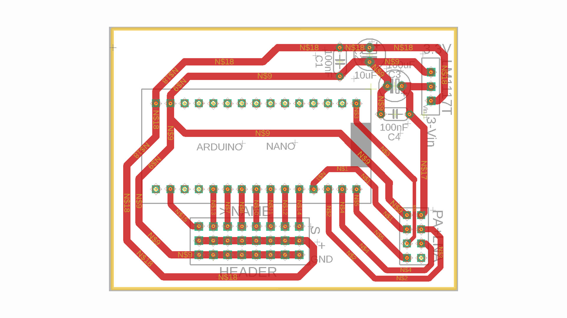
8 Kanal Versiyon için PDF ve Gerber dosyaları: https://drive.google.com/file/d/1Rkizn8hUWnudV3X0FFvIstjzWnkRgt7W/view?usp=sharing
PCB Plaket ölçüleri:
Verici: 122 x 75mm
Alıcı: 60 x 45mm
8 Kanal Verici için Arduino Nano Kodu:
// 8 Channel Transmitter | 8 Kanal Verici
// KendinYap Channel

  #include <SPI.h>
  #include <nRF24L01.h>
  #include <RF24.h>
  const uint64_t pipeOut = 0xABCDABCD71LL;         // NOTE: The address in the Transmitter and Receiver code must be the same "0xABCDABCD71LL" | Verici ve Alıcı kodundaki adres aynı olmalıdır
  RF24 radio(9, 10);                               // select CE,CSN pins | CE ve CSN pinlerin seçimi

  struct Signal {
  byte throttle;
  byte pitch;
  byte roll;
  byte yaw;
  byte aux1;
  byte aux2;
  byte aux3;
  byte aux4;
};
  Signal data;
  void ResetData()
{
  data.throttle = 0;
  data.pitch = 127;
  data.roll = 127;
  data.yaw = 127;
  data.aux1 = 0;
  data.aux2 = 0;
  data.aux3 = 0;
  data.aux4 = 0;
}
  void setup()
{
                                       // Configure the NRF24 module  | NRF24 modül konfigürasyonu
  radio.begin();
  radio.openWritingPipe(pipeOut);
  radio.setChannel(100);
  radio.setAutoAck(false);
  radio.setDataRate(RF24_250KBPS);    // The lowest data rate value for more stable communication  | Daha kararlı iletişim için en düşük veri hızı.
  radio.setPALevel(RF24_PA_MAX);      // Output power is set for maximum range  |  Çıkış gücü maksimum menzil için ayarlanıyor.
  radio.stopListening();              // Start the radio comunication for Transmitter | Verici için sinyal iletişimini başlatır.
  ResetData();

}
                                      // Joystick center and its borders | Joystick merkez ve sınırları
  int Border_Map(int val, int lower, int middle, int upper, bool reverse)
{
  val = constrain(val, lower, upper);
  if ( val < middle )
  val = map(val, lower, middle, 0, 128);
  else
  val = map(val, middle, upper, 128, 255);
  return ( reverse ? 255 - val : val );
}
  void loop()
{

  data.roll = Border_Map( analogRead(A7), 0, 512, 1023, true );        // CH1   Note: "true" or "false" for signal direction | "true" veya "false" sinyal yönünü belirler
  data.pitch = Border_Map( analogRead(A6), 0, 512, 1023, true );       // CH2
  data.throttle = Border_Map( analogRead(A3),0, 570, 800, true );      // CH3   Note: For Single side ESC | Tek yönlü ESC için
  // data.throttle = Border_Map( analogRead(A3),0, 512, 1023, true );  // CH3   Note: For Bidirectional ESC | Çift yönlü ESC için
  data.yaw = Border_Map( analogRead(A4), 0, 512, 1023, false );        // CH4
  data.aux1 = digitalRead(0);                                          // CH5
  data.aux2 = digitalRead(3);                                          // CH6
  data.aux3 = Border_Map( analogRead(A0),0, 512, 1023, true );         // CH7
  data.aux4 = Border_Map( analogRead(A1),0, 512, 1023, true );         // CH8

  radio.write(&data, sizeof(Signal));
}
8 Kanal Alıcı İçin Arduino Nano Kodu:
//  8-Channel Receiver | 8 Kanal Alıcı

#include <SPI.h>
#include <nRF24L01.h>
#include <RF24.h>
#include <Servo.h>

int ch_width_1 = 0;
int ch_width_2 = 0;
int ch_width_3 = 0;
int ch_width_4 = 0;
int ch_width_5 = 0;
int ch_width_6 = 0;

int ch_width_7 = 0;
int ch_width_8 = 0;

Servo ch1;
Servo ch2;
Servo ch3;
Servo ch4;
Servo ch5;
Servo ch6;

Servo ch7;
Servo ch8;

struct Signal {

byte throttle;
byte pitch;
byte roll;
byte yaw;
byte aux1;
byte aux2;

byte aux3;
byte aux4;

};

Signal data;

const uint64_t pipeIn = 0xABCDABCD71LL;
RF24 radio(9, 10);

void ResetData()
{

data.throttle = 0;                                         // Define the inicial value of each data input. | Veri girişlerinin başlangıç değerleri
data.roll = 127;
data.pitch = 127;
data.yaw = 127;
data.aux1 = 0;
data.aux2 = 0;

data.aux3 = 0;
data.aux4 = 0;

}

void setup()
{
                                                           // Set the pins for each PWM signal | Her bir PWM sinyal için pinler belirleniyor.
  ch1.attach(2);
  ch2.attach(3);
  ch3.attach(4);
  ch4.attach(5);
  ch5.attach(6);
  ch6.attach(7);

  ch7.attach(8);
  ch8.attach(0);

  ResetData();                                             // Configure the NRF24 module  | NRF24 Modül konfigürasyonu
  radio.begin();
  radio.openReadingPipe(1,pipeIn);
  radio.setChannel(100);
  radio.setAutoAck(false);
  radio.setDataRate(RF24_250KBPS);                         // The lowest data rate value for more stable communication  | Daha kararlı iletişim için en düşük veri hızı.
  radio.setPALevel(RF24_PA_MAX);                           // Output power is set for maximum |  Çıkış gücü maksimum için ayarlanıyor.
  radio.startListening();                                  // Start the radio comunication for receiver | Alıcı için sinyal iletişimini başlatır.

}

unsigned long lastRecvTime = 0;

void recvData()
{
while ( radio.available() ) {
radio.read(&data, sizeof(Signal));
lastRecvTime = millis();                                    // Receive the data | Data alınıyor
}
}

void loop()
{
recvData();
unsigned long now = millis();
if ( now - lastRecvTime > 1000 ) {
ResetData();                                                // Signal lost.. Reset data | Sinyal kayıpsa data resetleniyor
}

ch_width_1 = map(data.roll, 0, 255, 1000, 2000);
ch_width_2 = map(data.pitch, 0, 255, 1000, 2000);
ch_width_3 = map(data.throttle, 0, 255, 1000, 2000);
ch_width_4 = map(data.yaw, 0, 255, 1000, 2000);
ch_width_5 = map(data.aux1, 0, 1, 1000, 2000);
ch_width_6 = map(data.aux2, 0, 1, 1000, 2000);

ch_width_7 = map(data.aux3, 0, 255, 1000, 2000);
ch_width_8 = map(data.aux4, 0, 255, 1000, 2000);

ch1.writeMicroseconds(ch_width_1);                          // Write the PWM signal | PWM sinyaller çıkışlara gönderiliyor
ch2.writeMicroseconds(ch_width_2);
ch3.writeMicroseconds(ch_width_3);
ch4.writeMicroseconds(ch_width_4);
ch5.writeMicroseconds(ch_width_5);
ch6.writeMicroseconds(ch_width_6);

ch7.writeMicroseconds(ch_width_7);
ch8.writeMicroseconds(ch_width_8);

}
8 Kanal verici için gerekli iki adet 10K potansiyometre: https://s.click.aliexpress.com/e/_DkbmbTR
7. ve 8. kanal potansiyometre ile kontrol ediliyor. Potansları PCB üzerine yapıştırıcı ile dik bir şekilde yerleştirmek gerekiyor. Pot pinlerini L şeklinde bükebilirsiniz. Ama pinler kısa olduğu için kablo ile uzatmak gerekecektir.
_____________________________________________________________________
GENEL BİLGİLER:
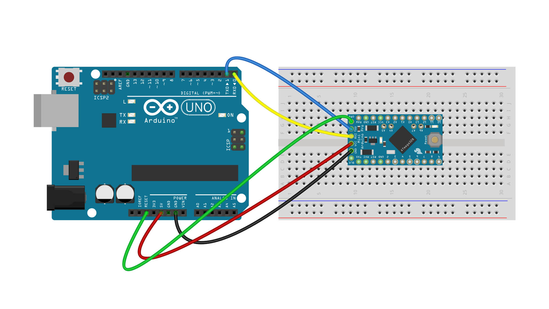
Kodları Arduino’ya yüklemeden önce gerekli kütüphane dosyalarını bilgisayarınıza indirmeniz gerekmektedir.
Kütüphane dosyası yoksa kurulum gerçekleşmeyecek ve hata oluşacaktır.
İndirmek için linkler …..:
Gerekli kütüphane dosyası:
SPI.h
nRF24L01.h
RF24.h
Servo.h
NRF24 Module library Files (Github page): https://github.com/nRF24/RF24
NRF24 Module library File (zip) : https://github.com/nRF24/RF24/archive/master.zip
Servo Library: https://www.arduinolibraries.info/libraries/servo
Arduino IDE nasıl kurulur? & Kütüphane dosyaları nasıl yüklenir?