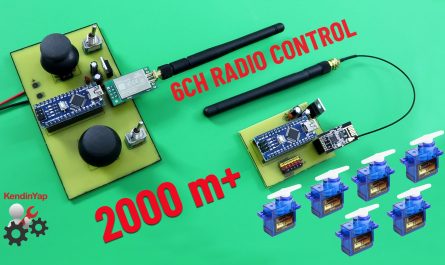
ESC kullanmadan motor hızını kontrol edebilen 4 kanallı bir uzaktan kumanda nasıl yapılır?
Tasarladığım 4 kanallı uzaktan kumandanın bir kanalı servo kontrolü içindir. İki kanal, iki farklı DC motoru kontrol edebilir. İleri-dur-geri komutlarıyla birlikte hız kontrolü sağlar. Bir kanal röleler içindir. Röleyi ışıkları veya çeşitli açma/kapama sistemlerini kontrol etmek için kullanabilirsiniz.
Çeşitli kara taşıtlarında kullanılabilir. Otomobiller, tanklar, tekneler ve benzeri araçlar için yeterlidir. Direksiyon veya dümen kontrolü servo ile sağlanır. Hareket gücü iki motor tarafından sağlanır. İki motor bağımsız olarak kontrol edilebildiğinden, tanklar gibi paletli araçlar için de uygundur.
Yerden havaya kontrol menzili yaklaşık 2000 metredir. Yüzeyde bu menzil 500-600 metredir. Elbette, bu menzil yalnızca ideal koşullar altında elde edilebilir. Verici için seçtiğim NRF24L01 modülü, 100mW gücünde E01-2G4M27D versiyonudur. Bu sayede tatmin edici kontrol mesafelerine ulaşabildim. Kara araçları için 200-300 metre bile fazlasıyla yeterlidir.
Profesyonel PCB ihtiyaçlarınız için JLCPCB . Kaliteli, Hızlı, Güvenli …
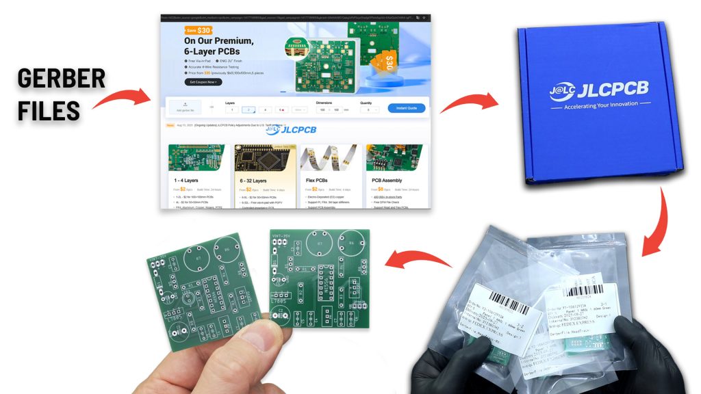
Get a limited-time $33 coupon for JLCPCB’s 6-layer PCBs- and order boards up to ıoox 100 mm for just $2.
Discover easy, affordable, and reliable multilayer PCB manufacturing with JLCPCB! Register now to get $70 new-customer coupons: https://jlcpcb.com/?from=RCMakerLab2
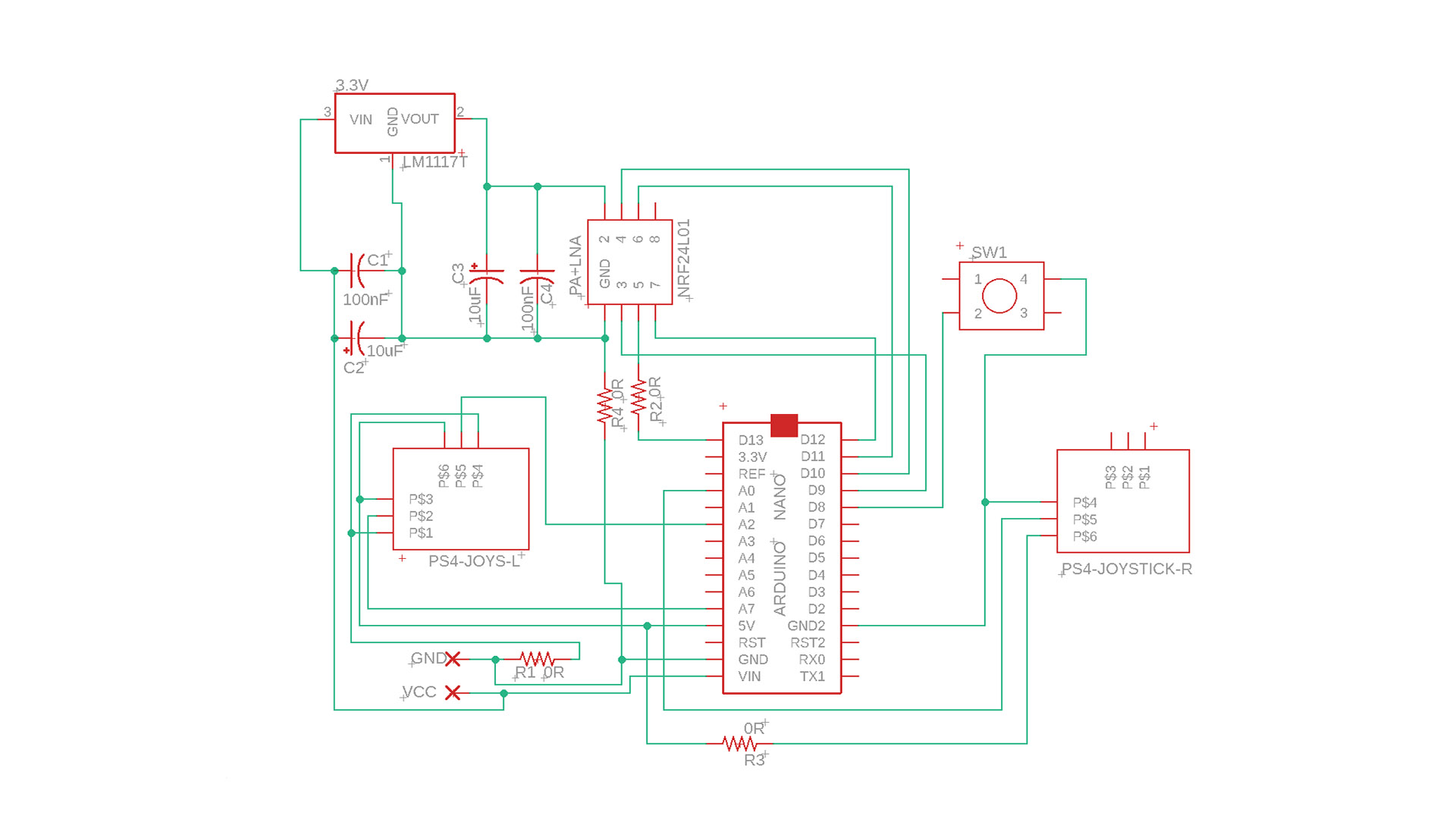
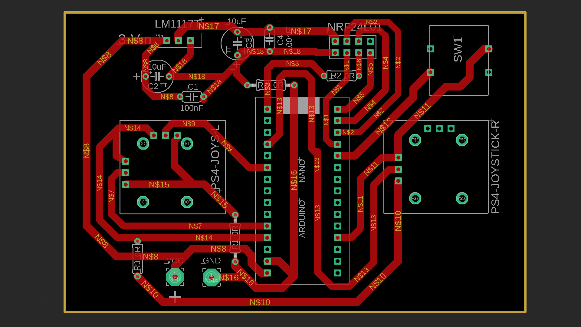
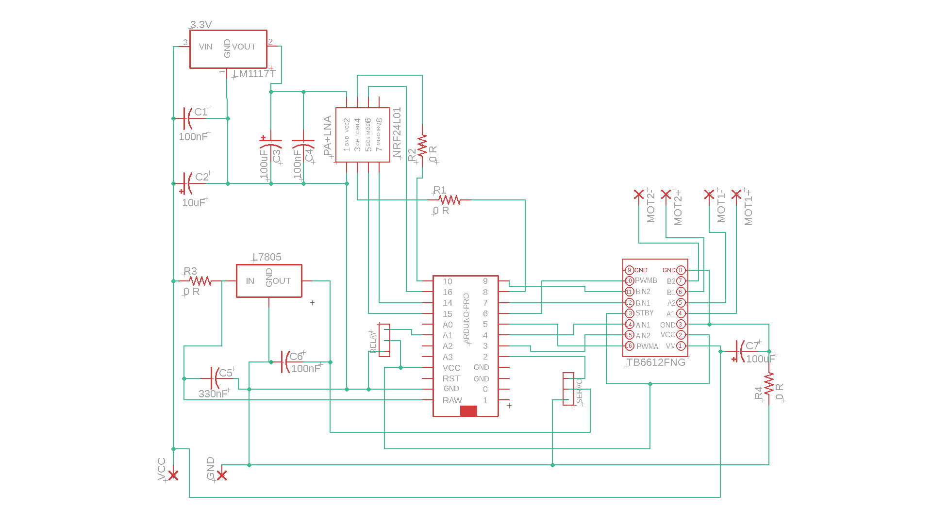
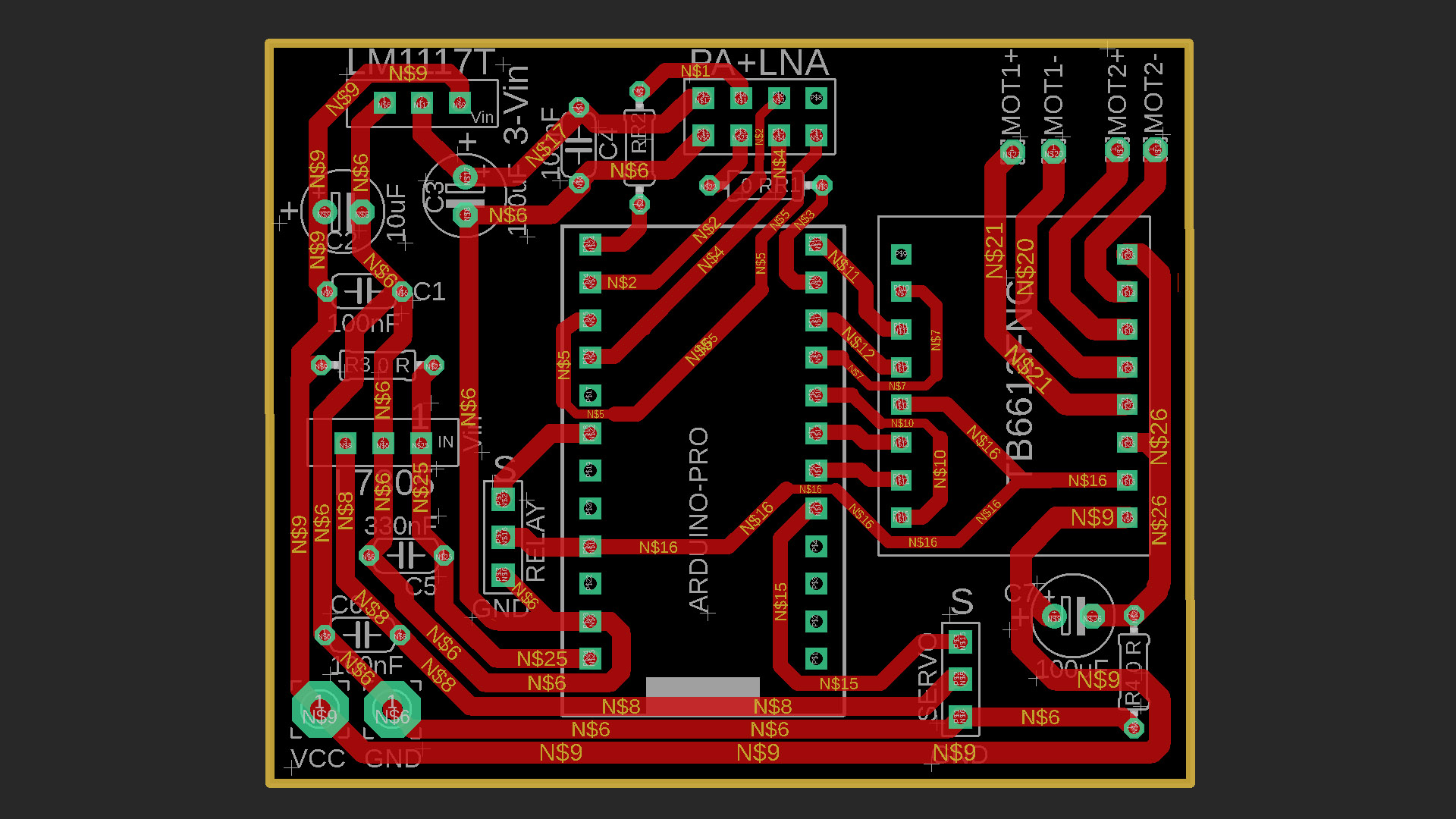
Verici ve Alıcı Devreleri:
PDF & Gerber & Kod Dosyaları: https://drive.google.com/file/d/1I7rujLnyVubDhHs3rglj73iU-c2BsaWs/view?usp=sharing
RC Verici Kodu (Arduino NANO için):
					// ============================================================
//  ByRCMakerLab
//  4 Kanal NRF24L01 Transmitter | Arduino Nano
//  Channel maps:
//    CH1 (throttle1) : A7  → Alıcı PWMA  (Motor A hız, ileri/stop/geri)
//    CH2 (throttle2) : A0  → Alıcı PWMB  (Motor B hız, ileri/stop/geri)
//    CH3 (yaw)       : A2  → Alıcı Servo (D2)
//    CH4 (aux1)      : D8  → Alıcı Röle  (A1) — toggle buton
//  NRF24 : CE=D9, CSN=D10
// ============================================================

#include <SPI.h>
#include <nRF24L01.h>
#include <RF24.h>

// ---------- NRF24 ----------
RF24 radio(9, 10);                          // CE, CSN
const uint64_t pipeOut = 0xABCDABCD71LL;

// ---------- Data packed ----------
struct Signal {
  byte throttle1;   // Motor A speed+direction  0-127 reward | 128 stop | 129-255 forward
  byte throttle2;   // Motor B
  byte yaw;         // Servo angle       0-255
  byte aux1;        // Röle toggle       0 or 1
};
Signal data;

// ---------- Button ----------
const int BTN_PIN      = 8;
bool      lastBtnState = HIGH;
bool      toggleState  = false;  // Current status of the relay.
unsigned long lastDebounce = 0;
const unsigned long DEBOUNCE_MS = 50;

void ResetData() {
  data.throttle1 = 127;   // center = stop
  data.throttle2 = 127;
  data.yaw       = 127;
  data.aux1      = 0;
}

// ---------------------------------------------------------------
// Potansiyometer → 0-255
//   Center area (deadband) → 127 (stop)
//   Back   → 0-126
//   Forward   → 128-255
// ---------------------------------------------------------------
byte MotorMap(int rawVal, bool reverse = false) {
  const int LOWER  = 0;
  const int MIDDLE = 512;
  const int UPPER  = 1023;
  const int DEAD   = 40;   // ±40 ADC deadband

  rawVal = constrain(rawVal, LOWER, UPPER);

  if (abs(rawVal - MIDDLE) <= DEAD) return 127;  // stopping area

  byte out;
  if (rawVal < MIDDLE)
    out = map(rawVal, LOWER, MIDDLE - DEAD, 0, 126);
  else
    out = map(rawVal, MIDDLE + DEAD, UPPER, 128, 255);

  return reverse ? (255 - out) : out;
}

// servo map 0-255 (no deadband)
byte ServoMap(int rawVal, bool reverse = false) {
  byte out = map(constrain(rawVal, 0, 1023), 0, 1023, 0, 255);
  return reverse ? (255 - out) : out;
}

void setup() {
  pinMode(BTN_PIN, INPUT_PULLUP);

  radio.begin();
  radio.openWritingPipe(pipeOut);
  radio.setChannel(100);
  radio.setAutoAck(false);
  radio.setDataRate(RF24_250KBPS);
  radio.setPALevel(RF24_PA_MAX);
  radio.stopListening();

  ResetData();
}

void loop() {
  // --- Motor A (A7) ---
  data.throttle1 = MotorMap(analogRead(A7), false);

  // --- Motor B (A0) ---
  data.throttle2 = MotorMap(analogRead(A0), false);

  // --- Servo (A2) ---
  data.yaw = ServoMap(analogRead(A2), false);

  // --- Röle butonu (D8) — toggle, debounce ---
  bool currentBtn = digitalRead(BTN_PIN);
  if (currentBtn == LOW && lastBtnState == HIGH) {
    if (millis() - lastDebounce > DEBOUNCE_MS) {
      toggleState = !toggleState;
      lastDebounce = millis();
    }
  }
  lastBtnState = currentBtn;
  data.aux1 = toggleState ? 1 : 0;

  // --- Gönder ---
  radio.write(&data, sizeof(Signal));
  delay(20);   // ~50 Hz update speed
}
Alıcı Kodu (Arduino Pro Micro için):
// ============================================================
// 4 Kanal NRF24L01 Receiver | Arduino Pro Micro
//
// TB6612FNG Motor Driver Pins:
// PWMA → D5 (Motor A speed PWM)
// AIN1 → D4 (Motor A direction)
// AIN2 → D3 (Motor A direction)
// PWMB → D6 (Motor B speed PWM)
// BIN1 → D7 (Motor B direction)
// BIN2 → D9 (Motor B direction)
//
// Diğer:
// Servo → D2
// Röle → A1
//
// NRF24 : CE=D8, CSN=D10
//
// Signal protocol (Signal from transmitter):
// 0-126 → backward (speed = 126-val → 126..1)
// 127 → Stop
// 128-255 → forward (speed = val-128 → 0..127) → PWM 0-254
// ============================================================
#include <SPI.h>
#include <nRF24L01.h>
#include <RF24.h>
#include <Servo.h>
// ---------- NRF24 ----------
RF24 radio(8, 10); // CE=D8, CSN=D10
const uint64_t pipeIn = 0xABCDABCD71LL;
// ---------- Data packed (same struct as the transmitter) ----------
struct Signal {
byte throttle1;
byte throttle2;
byte yaw;
byte aux1;
};
Signal data;
// ---------- Motor A — TB6612FNG ----------
const int PWMA = 5;
const int AIN1 = 4;
const int AIN2 = 3;
// ---------- Motor B — TB6612FNG ----------
const int PWMB = 6;
const int BIN1 = 7;
const int BIN2 = 9;
// ---------- Servo ----------
Servo myServo;
const int SERVO_PIN = 2;
// ---------- Relay ----------
const int RELAY_PIN = A1;
bool lastRelayCmd = false; // previous aux1 value (edge detection — optional)
// ---------- Disconnection safety ----------
unsigned long lastRecvTime = 0;
const unsigned long TIMEOUT_MS = 500; // Stop the motors if no signal is received within 500 ms.
// ---------------------------------------------------------------
// Motor A drive
// ---------------------------------------------------------------
void driveMotorA(byte val) {
if (val == 127) {
// Stop
analogWrite(PWMA, 0);
digitalWrite(AIN1, LOW);
digitalWrite(AIN2, LOW);
} else if (val > 127) {
// İleri
int pwm = map(val, 128, 255, 0, 255);
digitalWrite(AIN1, HIGH);
digitalWrite(AIN2, LOW);
analogWrite(PWMA, pwm);
} else {
// Geri
int pwm = map(val, 126, 0, 0, 255);
digitalWrite(AIN1, LOW);
digitalWrite(AIN2, HIGH);
analogWrite(PWMA, pwm);
}
}
// ---------------------------------------------------------------
// Motor B drive
// ---------------------------------------------------------------
void driveMotorB(byte val) {
if (val == 127) {
analogWrite(PWMB, 0);
digitalWrite(BIN1, LOW);
digitalWrite(BIN2, LOW);
} else if (val > 127) {
int pwm = map(val, 128, 255, 0, 255);
digitalWrite(BIN1, HIGH);
digitalWrite(BIN2, LOW);
analogWrite(PWMB, pwm);
} else {
int pwm = map(val, 126, 0, 0, 255);
digitalWrite(BIN1, LOW);
digitalWrite(BIN2, HIGH);
analogWrite(PWMB, pwm);
}
}
// ---------------------------------------------------------------
// Safe stop (when signal is interrupted)
// ---------------------------------------------------------------
void SafeStop() {
driveMotorA(127);
driveMotorB(127);
// The servo and relay remain in their final position
}
void setup() {
// Motor pinleri
pinMode(PWMA, OUTPUT);
pinMode(AIN1, OUTPUT);
pinMode(AIN2, OUTPUT);
pinMode(PWMB, OUTPUT);
pinMode(BIN1, OUTPUT);
pinMode(BIN2, OUTPUT);
// Röle
pinMode(RELAY_PIN, OUTPUT);
digitalWrite(RELAY_PIN, LOW);
// Servo
myServo.attach(SERVO_PIN);
myServo.write(90); // starting center
// NRF24
radio.begin();
radio.openReadingPipe(1, pipeIn);
radio.setChannel(100);
radio.setAutoAck(false);
radio.setDataRate(RF24_250KBPS);
radio.setPALevel(RF24_PA_MAX);
radio.startListening();
SafeStop();
}
void loop() {
// --- Veri al ---
if (radio.available()) {
radio.read(&data, sizeof(Signal));
lastRecvTime = millis();
// Motor A
driveMotorA(data.throttle1);
// Motor B
driveMotorB(data.throttle2);
// Servo: 0-255 → 0-180 derece
int servoAngle = map(data.yaw, 0, 255, 30, 150);
myServo.write(servoAngle);
// Röle: aux1 doğrudan HIGH/LOW
digitalWrite(RELAY_PIN, data.aux1 ? HIGH : LOW);
}
// --- Zaman aşımı kontrolü ---
if (millis() - lastRecvTime > TIMEOUT_MS) {
SafeStop();
}
}
Required Materials For Receiver and Transmitter:
NRF24L01 Module E01-ML01DP5
NRF24L01 GT-24 Modül
LM1117 3.3V Regulator
7805 5V Regulator
0R Direnç (Jumper Direnç)
TB6612FNG Motor Sürücü Modulü
47nf & 100nF Seramik kapasitör
330nF Seramik kapasitör
10uF & 100uF (16V) kapacitör
12×12 Tach Button (5 veya 6 mm)
2 pin JST&Kablo
2.54 Header pin
5V Röle
Tek taraflı bakır plaket
GENEl BİLGİ:
Arduino’ya kodları yüklemeden önce, gerekli kütüphane dosyalarını bilgisayarınıza indirmeniz ve Arduino/Library klasörüne kopyalamanız gerekir.
Kütüphane dosyaları yoksa, kurulum gerçekleşmez ve bir hata oluşur.
Gerekli Kütüphane Dosyaları:
SPI.h
nRF24L01.h
RF24.h
Servo.h
NRF24 Kütüphane Dosyaları İçin Linkler:
NRF24 Module library Files (Github page): https://github.com/nRF24/RF24
NRF24 Module library File (zip) : https://github.com/nRF24/RF24/archive/master.zip