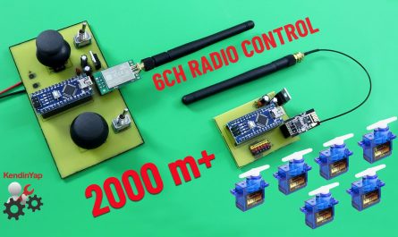
How to build a 4-channel remote control that can control motor speed without using an ESC?
The 4-channel remote I designed has one channel for servo control. Two channels, can control two different DC motors. It provides speed control along with forward-stop-reverse commands. One channel is for relays. You can use the relay to control lights or for various on/off systems.
It can be used in various surface vehicles. It is sufficient for cars, tanks, boats, and similar vehicles. Steering or rudder control is provided by servo. Movement power is provided by two motors. Since the two motors can be controlled independently, it is also suitable for tracked vehicles such as tanks.
The ground-to-air control range is approximately 2000 meters. On the surface, this range is 500-600 meters. Of course, this range can only be achieved under ideal conditions. The NRF24L01 module I chose for the transmitter is the E01-ML01DP5 version with 100mW power. This allowed me to achieve satisfactory control ranges.
JLCPCB for your professional PCB needs. Quality, Reliable, Fast …
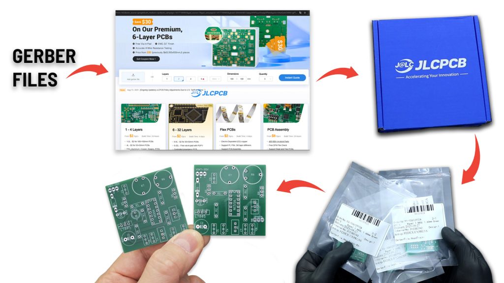
Get a limited-time $30 coupon for JLCPCB’s 6-layer PCBs- and order boards up to ıoox 100 mm for just $2.
Discover easy, affordable, and reliable multilayer PCB manufacturing with JLCPCB! Register now to get $123 new-customer coupons: https://jlcpcb.com/?from=RCMakerLab2
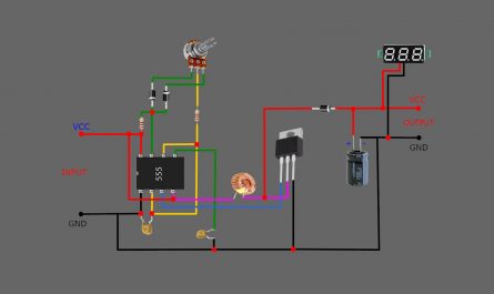
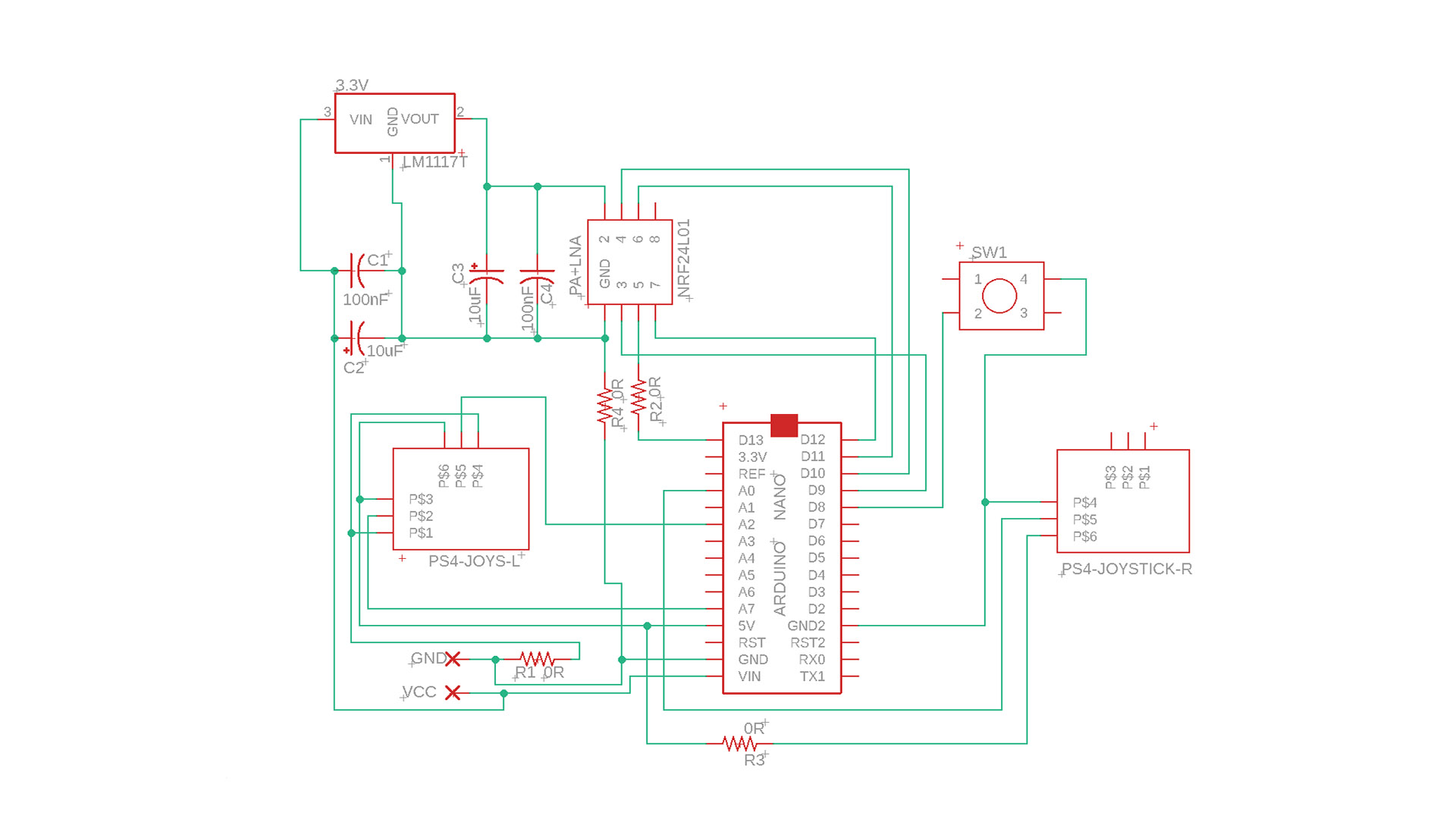
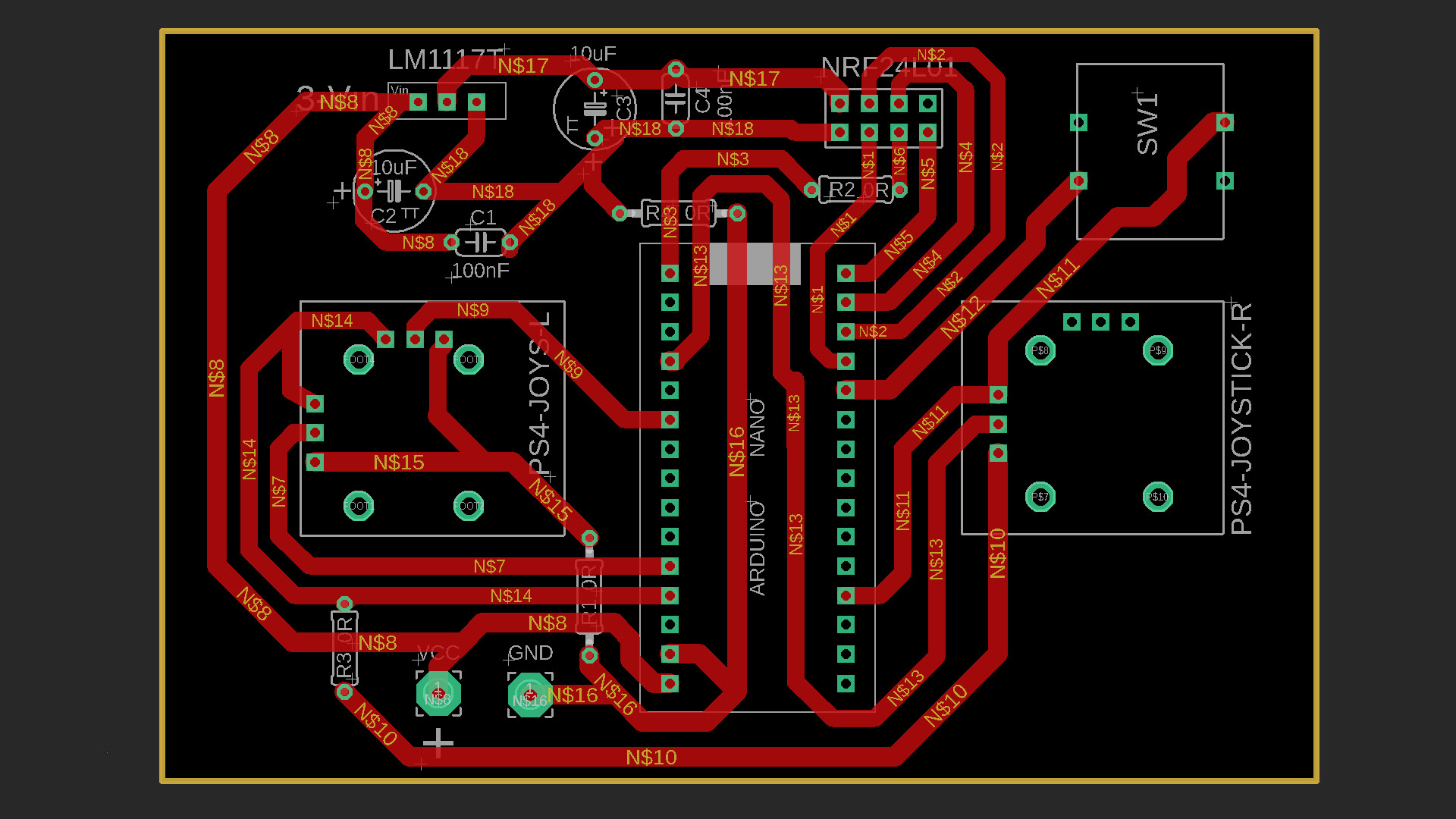
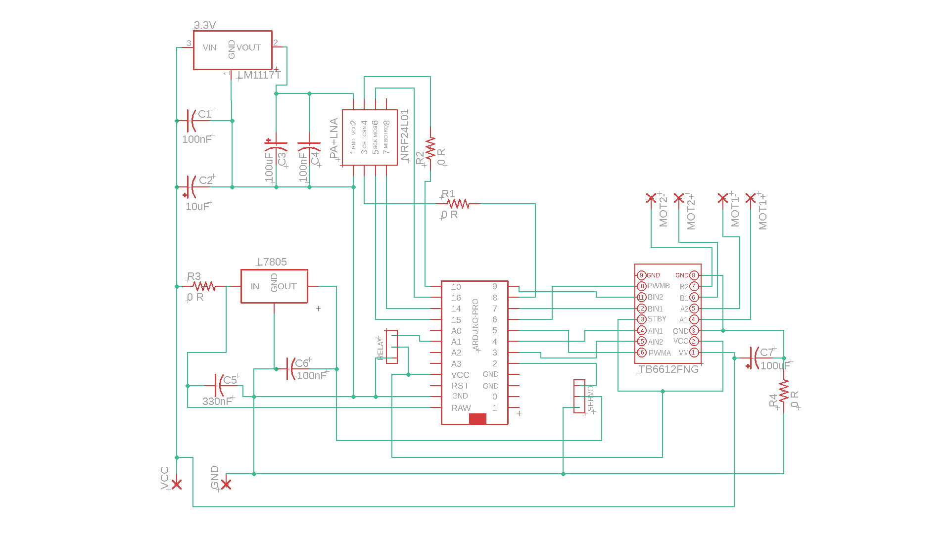
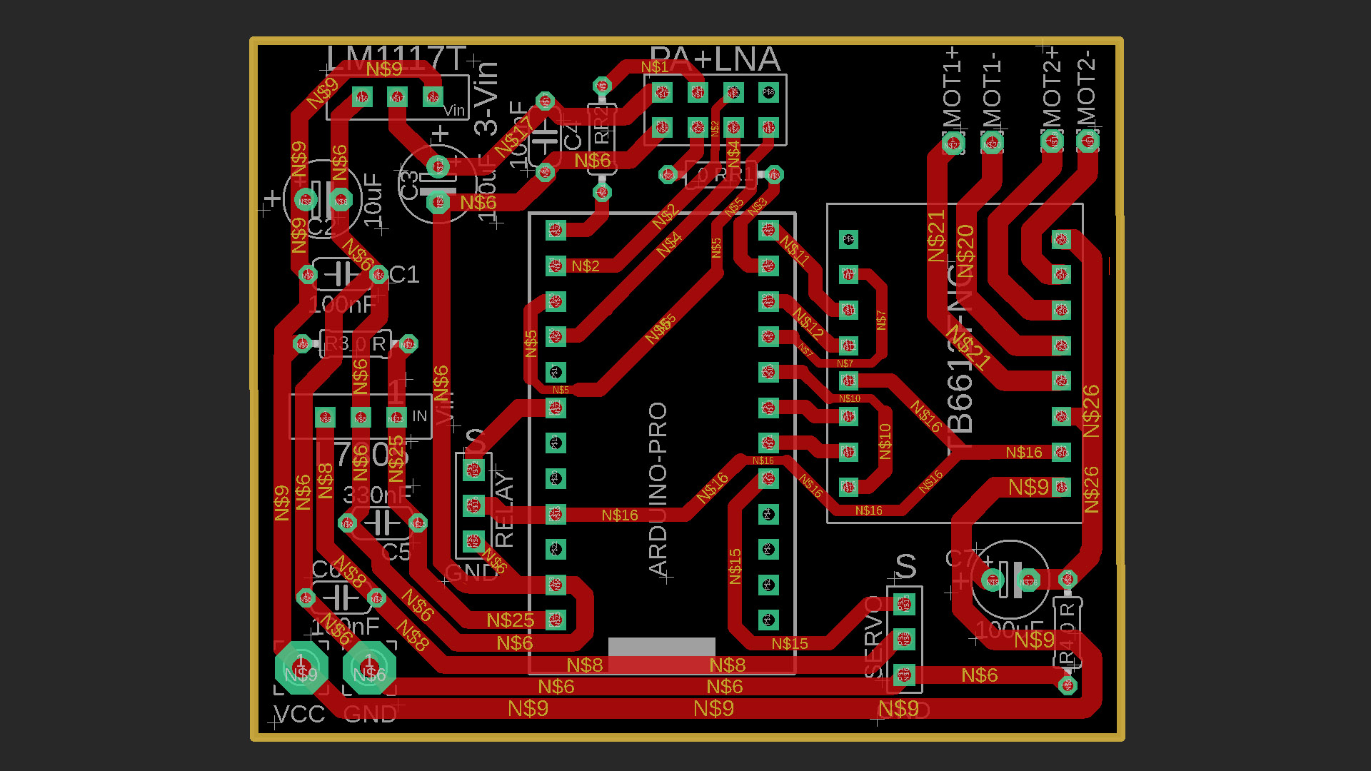
Transmitter and Receiver Circuits:
PDF & Gerber & Code Files: https://drive.google.com/file/d/1I7rujLnyVubDhHs3rglj73iU-c2BsaWs/view?usp=sharing
RC Transmitter Code For Arduino NANO:
					// ============================================================
//  ByRCMakerLab
//  4 Kanal NRF24L01 Transmitter | Arduino Nano
//  Channel maps:
//    CH1 (throttle1) : A7  → Alıcı PWMA  (Motor A hız, ileri/stop/geri)
//    CH2 (throttle2) : A0  → Alıcı PWMB  (Motor B hız, ileri/stop/geri)
//    CH3 (yaw)       : A2  → Alıcı Servo (D2)
//    CH4 (aux1)      : D8  → Alıcı Röle  (A1) — toggle buton
//  NRF24 : CE=D9, CSN=D10
// ============================================================

#include <SPI.h>
#include <nRF24L01.h>
#include <RF24.h>

// ---------- NRF24 ----------
RF24 radio(9, 10);                          // CE, CSN
const uint64_t pipeOut = 0xABCDABCD71LL;

// ---------- Data packed ----------
struct Signal {
  byte throttle1;   // Motor A speed+direction  0-127 reward | 128 stop | 129-255 forward
  byte throttle2;   // Motor B
  byte yaw;         // Servo angle       0-255
  byte aux1;        // Röle toggle       0 or 1
};
Signal data;

// ---------- Button ----------
const int BTN_PIN      = 8;
bool      lastBtnState = HIGH;
bool      toggleState  = false;  // Current status of the relay.
unsigned long lastDebounce = 0;
const unsigned long DEBOUNCE_MS = 50;

void ResetData() {
  data.throttle1 = 127;   // center = stop
  data.throttle2 = 127;
  data.yaw       = 127;
  data.aux1      = 0;
}

// ---------------------------------------------------------------
// Potansiyometer → 0-255
//   Center area (deadband) → 127 (stop)
//   Back   → 0-126
//   Forward   → 128-255
// ---------------------------------------------------------------
byte MotorMap(int rawVal, bool reverse = false) {
  const int LOWER  = 0;
  const int MIDDLE = 512;
  const int UPPER  = 1023;
  const int DEAD   = 40;   // ±40 ADC deadband

  rawVal = constrain(rawVal, LOWER, UPPER);

  if (abs(rawVal - MIDDLE) <= DEAD) return 127;  // stopping area

  byte out;
  if (rawVal < MIDDLE)
    out = map(rawVal, LOWER, MIDDLE - DEAD, 0, 126);
  else
    out = map(rawVal, MIDDLE + DEAD, UPPER, 128, 255);

  return reverse ? (255 - out) : out;
}

// servo map 0-255 (no deadband)
byte ServoMap(int rawVal, bool reverse = false) {
  byte out = map(constrain(rawVal, 0, 1023), 0, 1023, 0, 255);
  return reverse ? (255 - out) : out;
}

void setup() {
  pinMode(BTN_PIN, INPUT_PULLUP);

  radio.begin();
  radio.openWritingPipe(pipeOut);
  radio.setChannel(100);
  radio.setAutoAck(false);
  radio.setDataRate(RF24_250KBPS);
  radio.setPALevel(RF24_PA_MAX);
  radio.stopListening();

  ResetData();
}

void loop() {
  // --- Motor A (A7) ---
  data.throttle1 = MotorMap(analogRead(A7), false);

  // --- Motor B (A0) ---
  data.throttle2 = MotorMap(analogRead(A0), false);

  // --- Servo (A2) ---
  data.yaw = ServoMap(analogRead(A2), false);

  // --- Röle butonu (D8) — toggle, debounce ---
  bool currentBtn = digitalRead(BTN_PIN);
  if (currentBtn == LOW && lastBtnState == HIGH) {
    if (millis() - lastDebounce > DEBOUNCE_MS) {
      toggleState = !toggleState;
      lastDebounce = millis();
    }
  }
  lastBtnState = currentBtn;
  data.aux1 = toggleState ? 1 : 0;

  // --- Gönder ---
  radio.write(&data, sizeof(Signal));
  delay(20);   // ~50 Hz update speed
}
Receiver Code For Arduino Pro Micro:
// ============================================================
// 4 Kanal NRF24L01 Receiver | Arduino Pro Micro
//
// TB6612FNG Motor Driver Pins:
// PWMA → D5 (Motor A speed PWM)
// AIN1 → D4 (Motor A direction)
// AIN2 → D3 (Motor A direction)
// PWMB → D6 (Motor B speed PWM)
// BIN1 → D7 (Motor B direction)
// BIN2 → D9 (Motor B direction)
//
// Diğer:
// Servo → D2
// Röle → A1
//
// NRF24 : CE=D8, CSN=D10
//
// Signal protocol (Signal from transmitter):
// 0-126 → backward (speed = 126-val → 126..1)
// 127 → Stop
// 128-255 → forward (speed = val-128 → 0..127) → PWM 0-254
// ============================================================
#include <SPI.h>
#include <nRF24L01.h>
#include <RF24.h>
#include <Servo.h>
// ---------- NRF24 ----------
RF24 radio(8, 10); // CE=D8, CSN=D10
const uint64_t pipeIn = 0xABCDABCD71LL;
// ---------- Data packed (same struct as the transmitter) ----------
struct Signal {
byte throttle1;
byte throttle2;
byte yaw;
byte aux1;
};
Signal data;
// ---------- Motor A — TB6612FNG ----------
const int PWMA = 5;
const int AIN1 = 4;
const int AIN2 = 3;
// ---------- Motor B — TB6612FNG ----------
const int PWMB = 6;
const int BIN1 = 7;
const int BIN2 = 9;
// ---------- Servo ----------
Servo myServo;
const int SERVO_PIN = 2;
// ---------- Relay ----------
const int RELAY_PIN = A1;
bool lastRelayCmd = false; // previous aux1 value (edge detection — optional)
// ---------- Disconnection safety ----------
unsigned long lastRecvTime = 0;
const unsigned long TIMEOUT_MS = 500; // Stop the motors if no signal is received within 500 ms.
// ---------------------------------------------------------------
// Motor A drive
// ---------------------------------------------------------------
void driveMotorA(byte val) {
if (val == 127) {
// Stop
analogWrite(PWMA, 0);
digitalWrite(AIN1, LOW);
digitalWrite(AIN2, LOW);
} else if (val > 127) {
// İleri
int pwm = map(val, 128, 255, 0, 255);
digitalWrite(AIN1, HIGH);
digitalWrite(AIN2, LOW);
analogWrite(PWMA, pwm);
} else {
// Geri
int pwm = map(val, 126, 0, 0, 255);
digitalWrite(AIN1, LOW);
digitalWrite(AIN2, HIGH);
analogWrite(PWMA, pwm);
}
}
// ---------------------------------------------------------------
// Motor B drive
// ---------------------------------------------------------------
void driveMotorB(byte val) {
if (val == 127) {
analogWrite(PWMB, 0);
digitalWrite(BIN1, LOW);
digitalWrite(BIN2, LOW);
} else if (val > 127) {
int pwm = map(val, 128, 255, 0, 255);
digitalWrite(BIN1, HIGH);
digitalWrite(BIN2, LOW);
analogWrite(PWMB, pwm);
} else {
int pwm = map(val, 126, 0, 0, 255);
digitalWrite(BIN1, LOW);
digitalWrite(BIN2, HIGH);
analogWrite(PWMB, pwm);
}
}
// ---------------------------------------------------------------
// Safe stop (when signal is interrupted)
// ---------------------------------------------------------------
void SafeStop() {
driveMotorA(127);
driveMotorB(127);
// The servo and relay remain in their final position
}
void setup() {
// Motor pinleri
pinMode(PWMA, OUTPUT);
pinMode(AIN1, OUTPUT);
pinMode(AIN2, OUTPUT);
pinMode(PWMB, OUTPUT);
pinMode(BIN1, OUTPUT);
pinMode(BIN2, OUTPUT);
// Röle
pinMode(RELAY_PIN, OUTPUT);
digitalWrite(RELAY_PIN, LOW);
// Servo
myServo.attach(SERVO_PIN);
myServo.write(90); // starting center
// NRF24
radio.begin();
radio.openReadingPipe(1, pipeIn);
radio.setChannel(100);
radio.setAutoAck(false);
radio.setDataRate(RF24_250KBPS);
radio.setPALevel(RF24_PA_MAX);
radio.startListening();
SafeStop();
}
void loop() {
// --- Veri al ---
if (radio.available()) {
radio.read(&data, sizeof(Signal));
lastRecvTime = millis();
// Motor A
driveMotorA(data.throttle1);
// Motor B
driveMotorB(data.throttle2);
// Servo: 0-255 → 0-180 derece
int servoAngle = map(data.yaw, 0, 255, 30, 150);
myServo.write(servoAngle);
// Röle: aux1 doğrudan HIGH/LOW
digitalWrite(RELAY_PIN, data.aux1 ? HIGH : LOW);
}
// --- Zaman aşımı kontrolü ---
if (millis() - lastRecvTime > TIMEOUT_MS) {
SafeStop();
}
}
Required Materials For Receiver and Transmitter:
Arduino Pro Micro (5V): https://s.click.aliexpress.com/e/_c3J6yk7f OR https://s.click.aliexpress.com/e/_c3xktWgt
NRF24L01 Module E01-ML01DP5: https://s.click.aliexpress.com/e/_c3AOFuAB
NRF24L01 GT-24 Module: https://s.click.aliexpress.com/e/_c3FSPsh9
LM1117 3.3V Regulator: https://s.click.aliexpress.com/e/_c3Uf57aT
7805 5V Regulator: https://s.click.aliexpress.com/e/_c2JB9Ijv
0R Resistor: https://s.click.aliexpress.com/e/_c3415ZOb
TB6612FNG Motor Driver Module: https://s.click.aliexpress.com/e/_c3f9qcG7
47nf & 100nF Ceramic capacitors: https://s.click.aliexpress.com/e/_c4o6mz0n
330nF ceramic capacitor: https://s.click.aliexpress.com/e/_c4Oa9ExD
10uF & 100uF capacitors (16V): https://s.click.aliexpress.com/e/_c3WpDWyF
12×12 Tach Button (5 or 6): https://s.click.aliexpress.com/e/_c3h48c8x
2 pin JST&Cable: https://s.click.aliexpress.com/e/_c3IrrBfz
2.54 Header Pin : https://s.click.aliexpress.com/e/_c3aRosh3
5V Relay: https://s.click.aliexpress.com/e/_c3ZGbMOr
Copper Board (Single side): https://s.click.aliexpress.com/e/_c3JlJSjv
GENERAL INFO:
Before uploading the codes to Arduino, you need to download the necessary library files to your computer.
If there are no library files, the installation will not occur and an error will occur.
Required library file:
SPI.h
nRF24L01.h
RF24.h
Servo.h
NRF24 Module Library File Links for download :
NRF24 Module library Files (Github page): https://github.com/nRF24/RF24
NRF24 Module library File (zip) : https://github.com/nRF24/RF24/archive/master.zip