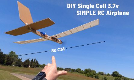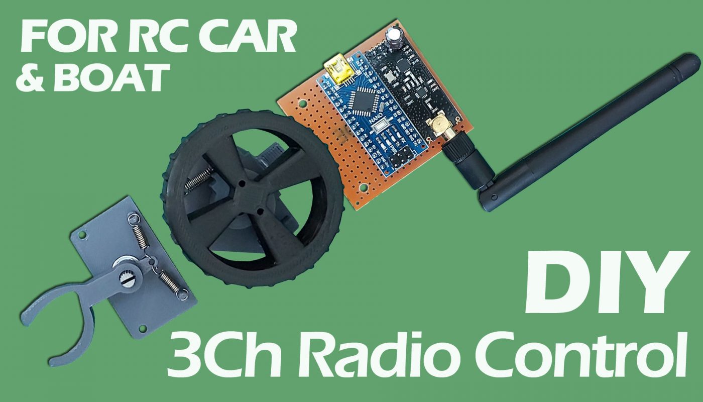
Model araba ve tekneler için 3 kanallı uzaktan kumanda yapımı.
Gerekli Malzemeler:
Arduino Nano
Arduino RF NANO
NRF24L01 + PA Wireless Modul
Delikli Plaket
100uF Kondansatör
2.54mm Header Pin
680R Direnç:
5mm LED
Rocker Switch
PLA Filament
Servo kablosu
15mm gerdirme yayı (Çekme yay)
STL Files: https://drive.google.com/file/d/1xsQZGecMFXOWbQH1PZuGSjoayJRfRPIG/view?usp=sharing
ALICI:
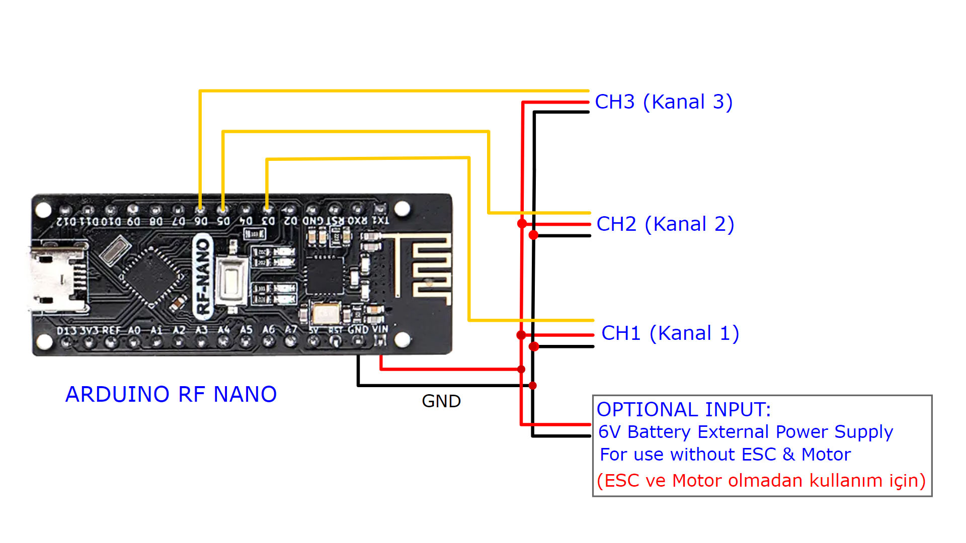
Arduino RF Nano için Alıcı kodu:
//  3 Channel Receiver | 3 Kanal Alıcı
//  PWM output on pins D3, D5, D6 (Çıkış pinleri)

#include <SPI.h>
#include <nRF24L01.h>
#include <RF24.h>
#include <Servo.h>

int ch_width_1 = 0;
int ch_width_2 = 0;
int ch_width_3 = 0;

Servo ch1;
Servo ch2;
Servo ch3;

struct Signal {
byte throttle;
byte steering;
byte aux1;

};

Signal data;

const uint64_t pipeIn = 0xE9E8F0F0E1LL;
RF24 radio(10, 9);

void ResetData()
{
// Define the inicial value of each data input. | Veri girişlerinin başlangıç değerleri
// The middle position for Potenciometers | Potansiyometreler için orta konum
data.steering = 127;   // Center | Merkez
data.throttle = 127;   // Motor Stop | Motor Kapalı
data.aux1 = 0;         // Center | Merkez
}

void setup()
{
  //Set the pins for each PWM signal | Her bir PWM sinyal için pinler belirleniyor.

  ch1.attach(3);
  ch2.attach(5);
  ch3.attach(6);

  //Configure the NRF24 module
  ResetData();
  radio.begin();
  radio.openReadingPipe(1,pipeIn);
  radio.setAutoAck(false);
  radio.setDataRate(RF24_250KBPS);
  radio.setPALevel(RF24_PA_MAX);
  radio.startListening(); //start the radio comunication for receiver | Alıcı olarak sinyal iletişimi başlatılıyor
}

unsigned long lastRecvTime = 0;

void recvData()
{
while ( radio.available() ) {
radio.read(&data, sizeof(Signal));
lastRecvTime = millis();   // receive the data | data alınıyor
}
}
void loop()
{
recvData();
unsigned long now = millis();
if ( now - lastRecvTime > 1000 ) {
ResetData(); // Signal lost.. Reset data | Sinyal kayıpsa data resetleniyor
}

ch_width_1 = map(data.steering, 0, 255, 1000, 2000);     // pin D3 (PWM signal)
ch_width_2 = map(data.throttle, 0, 255, 800, 2200);     // pin D5 (PWM signal)
ch_width_3 = map(data.aux1, 0, 1, 1000, 2000);          // pin D6 (PWM signal)

   // Write the PWM signal | PWM sinyaller çıkışlara gönderiliyor
ch1.writeMicroseconds(ch_width_1);
ch2.writeMicroseconds(ch_width_2);
ch3.writeMicroseconds(ch_width_3);
}
VERİCİ:
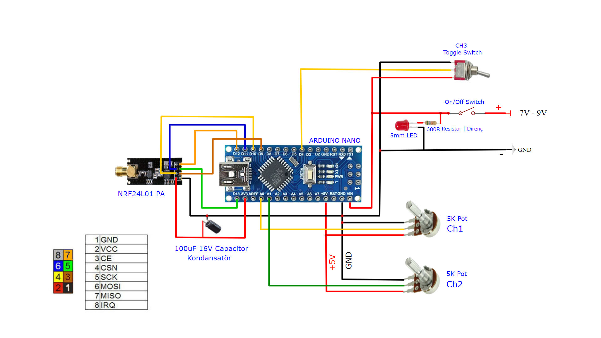
Verici kodu Arduino Nano için:
// 3 Channel Transmitter | 3 Kanal Verici
#include <SPI.h>
#include <nRF24L01.h>
#include <RF24.h>
const uint64_t pipeOut = 0xE9E8F0F0E1LL; // Match key | Eşleşme anahtarı
RF24 radio(9, 10); // Select CE,CSN pin | CE ve CSN pinlerin seçimi
struct Signal {
byte throttle;
byte steering;
byte aux1;

};
Signal data;
void ResetData()
{
data.throttle = 127; // Motor stop | Motor Kapalı (Signal lost position | sinyal kesildiğindeki pozisyon)
data.steering = 127; // Center | Merkez (Signal lost position | sinyal kesildiğindeki pozisyon)
data.aux1 = 0; // (Signal lost position | sinyal kesildiğindeki pozisyon)

}
void setup()
{
//Start everything up
radio.begin();
radio.openWritingPipe(pipeOut);
radio.setAutoAck(false);
radio.setDataRate(RF24_250KBPS);
radio.setPALevel(RF24_PA_MAX);
radio.stopListening(); //start the radio comunication for Receiver | Verici olarak sinyal iletişimi başlatılıyor
ResetData();

}
// Joystick center and it's borders | Joystick merkez ve sınırları
int mapJoystickValues(int val, int lower, int middle, int upper, bool reverse)
{
val = constrain(val, lower, upper);
if ( val < middle )
val = map(val, lower, middle, 0, 128);
else
val = map(val, middle, upper, 128, 255);
return ( reverse ? 255 - val : val );
}
void loop()
{
// Control Stick Calibration | Kumanda Kol Kalibrasyonları
// Setting may be required for the correct values of the control levers. | Kontrol kollarının doğru değerleri için ayar gerekebilir.

data.steering = mapJoystickValues( analogRead(A0), 200, 460, 650, true ); // "true" or "false" for servo direction | "true" veya "false" servo yönünü belirler
data.throttle = mapJoystickValues( analogRead(A1), 200, 440,670, true ); // "true" or "false" for signal direction | "true" veya "false" sinyal yönünü belirler
data.aux1 = digitalRead(4);
radio.write(&data, sizeof(Signal));
}
Kodları ARDUINO ya yükleyebilmeniz için temel adımlar:
1- Arduino IDE uygulamasını www.arduino.cc adresinden indirin.
2- Kodun üst satırındaki include ile başlayan satırlarda “.h” uzantılı dosyaları bilgisyarınıza indirin. (Bu dosyalar Kütüphane dosyalarıdır. Google da isimleri ile arayabilir ve kolayca bulabilirsiniz.)
3- Bu dosyaları “Belgeler/Arduino/Libraries” klasörüne kopyalayın.
4- Arduino IDE yi çalıştırın.
5- Arduino IDE ye kodu kopyalayın.
6- Kodu kaydedin.
7- Arduinoyu USB kablo ile bilgisayarınıza bağlayın.
8- Araçlar menüsünden Arduino cinsini ve bağlantı portunu seçin.
9- Kodu arduinoya yükleyin.
Örnek kütüphane dosyası: NRF24L01 için gerekli kütüphane linki: https://github.com/maniacbug/RF24 (Arduino kartına göre farklı versiyon kütüphane dosyaları gerekebilir. Deneyerek bulunabilir)