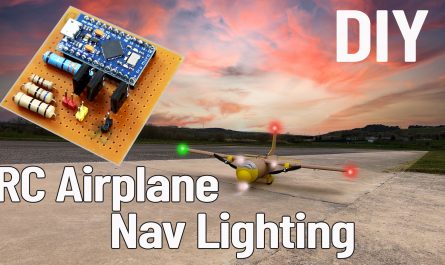
Head Tracking System for your FPV models.
The circuit consists of three main parts: a transmitter, a receiver, and the mechanical structure that converts signals from the receiver into movement using servos.
The mechanical structure has two axes: up-down and left-right. These movements are achieved with two servos. I used inexpensive micro servos in the tests I conducted in the video. You can achieve smoother movements with high-quality servos.
The transmitter reads the position information provided by the MPU6050 gyro module via an Arduino Pro Micro. It processes the data and sends it to the receiver via the NRF24 module.
To achieve maximum range, I chose the E01-2G4M27D as the communication module. This module has a 500mW output power.
Theoretically, it provides a range of 5 km. In real life, due to some voltage restrictions and the default antenna, the maximum range is approximately 2.5-3 km.
For maximum range, a 5 dBi antenna should be used and the antenna should be at least 250cm high (in open terrain under ideal weather conditions).
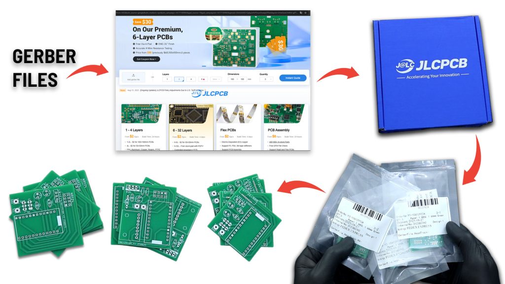
I needed PCBs for the transmitter and receiver circuits I was designing. I chose JLCPCB for PCB manufacturing.
After placing my order, my PCBs were prepared and shipped within 24 hours. The PCBs arrived 5-6 days later.
The PCBs are truly high quality. They boosted my motivation for my upcoming projects.
I thank JLCPCB for their high-quality and fast service.
You can reach JLCPB through the affiliate link below.
Discover Easy, Affordable, and Reliable PCB manufacturing with JLCPCB!Register to get $70 New customer coupons: https://jlcpcb.com/?from=KendinYap
Transmitter Circuit Needs:
* NRF24L01 PA LNA (E01-2G4M27D): https://s.click.aliexpress.com/e/_oDdE40B
OR https://s.click.aliexpress.com/e/_onkamdt
* LM350T : https://s.click.aliexpress.com/e/_olO9HRt
* Capacitors 100uF (1 pcs): https://s.click.aliexpress.com/e/_oCXjoHZ
* Capacitor 100nF 104 (1 pcs): https://s.click.aliexpress.com/e/_omwl5j1
* Resistors (270R , 470R): https://s.click.aliexpress.com/e/_ooezndl
* JST 2-Pin : https://s.click.aliexpress.com/e/_ooekDr1
TRANSMITTER CODE:
					// FPV HEAD TRACKING TRANSMITTER CODE  |  VERİCİ KODU
// BY KendinYap

#include <Wire.h>
#include "MPU6050_6Axis_MotionApps20.h"
#include <SPI.h>
#include <nRF24L01.h>
#include <RF24.h>
#include <Servo.h>

/* --- NRF24L01 Setup --- */
RF24 radio(8, 10);
const byte address[6] = "00001";

struct Data_Package {
  byte pitch;
  byte yaw;
  bool calibrationDone;
};
Data_Package data;

/* --- MPU6050 Setup --- */
MPU6050 mpu;
#define INTERRUPT_PIN 2
bool dmpReady = false;
uint8_t mpuIntStatus;
uint16_t packetSize;
uint8_t fifoBuffer[64];
Quaternion q;
VectorFloat gravity;
float ypr[3];
volatile bool mpuInterrupt = false;

/* --- Servo Setup --- */
Servo pitchServo;
Servo yawServo;
#define PITCH_SERVO_PIN 3
#define YAW_SERVO_PIN 4

void dmpDataReady() {
  mpuInterrupt = true;
}

void resetData() {
  data.pitch = 127;
  data.yaw = 127;
  data.calibrationDone = false;
}

void setup() {
  Serial.begin(115200);
  Wire.begin();
  Wire.setClock(400000);

  Serial.println(F("Initializing MPU6050..."));
  mpu.initialize();
  pinMode(INTERRUPT_PIN, INPUT);

  if (!mpu.testConnection()) {
    Serial.println(F("MPU6050 connection failed"));
    while (true);
  }

  Serial.println(F("MPU6050 connection successful"));
  uint8_t devStatus = mpu.dmpInitialize();

  if (devStatus == 0) {
    Serial.println(F("Calibrating MPU6050..."));
    mpu.CalibrateAccel(6);
    mpu.CalibrateGyro(6);
    mpu.setDMPEnabled(true);
    attachInterrupt(digitalPinToInterrupt(INTERRUPT_PIN), dmpDataReady, RISING);
    dmpReady = true;
    packetSize = mpu.dmpGetFIFOPacketSize();

    data.calibrationDone = true;
    for (int i = 0; i < 5; i++) {
      if (radio.write(&data, sizeof(Data_Package))) {
        Serial.println(F("Calibration done signal sent!"));
        break;
      }
      delay(200);
    }
    delay(1000);
    data.calibrationDone = false;

    pitchServo.attach(PITCH_SERVO_PIN);
    yawServo.attach(YAW_SERVO_PIN);
    pitchServo.write(90 + 60);
    delay(500);
    yawServo.write(90 + 60);
    delay(500);
    pitchServo.write(90);
    delay(500);
    yawServo.write(90);
  } else {
    Serial.print(F("DMP Initialization failed (code "));
    Serial.print(devStatus);
    Serial.println(F(")"));
  }

  radio.begin();
  radio.openWritingPipe(address);
  radio.setChannel(120);
  radio.setAutoAck(false);
  radio.setDataRate(RF24_250KBPS);
  radio.setPALevel(RF24_PA_MAX);
  radio.stopListening();
  resetData();
}

void loop() {
  if (!dmpReady) return;

  if (mpuInterrupt || mpu.getFIFOCount() >= packetSize) {
    mpuInterrupt = false;
    mpuIntStatus = mpu.getIntStatus();

    if ((mpuIntStatus & 0x10) || mpu.getFIFOCount() == 1024) {
      mpu.resetFIFO();
      Serial.println("FIFO overflow!");
      return;
    }

    if (mpu.dmpGetCurrentFIFOPacket(fifoBuffer)) {
      mpu.dmpGetQuaternion(&q, fifoBuffer);
      mpu.dmpGetGravity(&gravity, &q);
      mpu.dmpGetYawPitchRoll(ypr, &q, &gravity);

      data.yaw = constrain(map(ypr[0] * 180 / M_PI, 90, -90, 0, 255), 0, 255);
      data.pitch = constrain(map(ypr[2] * 180 / M_PI, 90, -90, 0, 255), 0, 255);

      Serial.print("Yaw: ");
      Serial.print(data.yaw);
      Serial.print(" Pitch: ");
      Serial.println(data.pitch);

      for (int i = 0; i < 3; i++) {
        if (radio.write(&data, sizeof(Data_Package))) {
          Serial.println("Data sent successfully");
          break;
        }
        delay(100);
      }
    }
  }
}
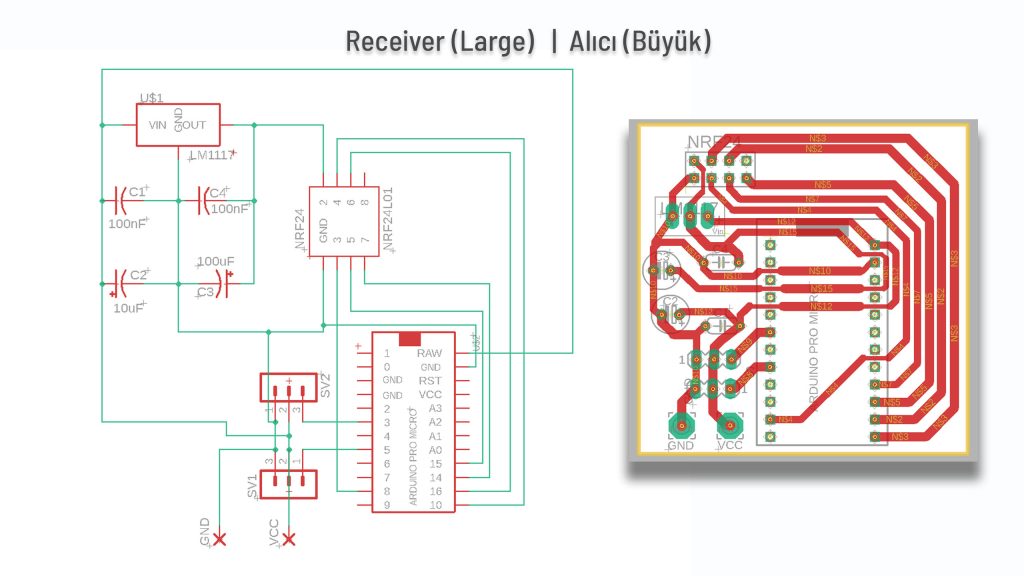
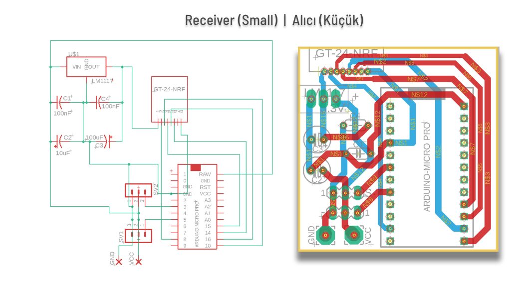
Receiver Circuit Needs:
* GT-24 Mini NRF24L01+PA+LNA (With Antenna): https://s.click.aliexpress.com/e/_oC5zVIr
* GT-24 NRF24L01+PA+LNA: https://s.click.aliexpress.com/e/_oC5zVIr
* LM1117 3.3V: https://s.click.aliexpress.com/e/_o2c26KT
* Capacitors 10uF (2 pcs), 100uF (2 pcs): https://s.click.aliexpress.com/e/_oCXjoHZ
* Capacitor 100nF 104 (4 pcs): https://s.click.aliexpress.com/e/_omwl5j1
* Y-Type & Extension Cables: https://s.click.aliexpress.com/e/_oDqhTNN
RECEIVER CODE:
The same code is loaded for both large and small receivers.
FPV Head Tracking Transmitter and Receiver codes:
					// FPV HEAD TRACKING RECEIVER CODE  |  ALICI KODU
// BY KendinYap

#include <SPI.h>
#include <nRF24L01.h>
#include <RF24.h>
#include <Servo.h>

// Servo tanımlamaları
Servo yawServo;
Servo pitchServo;

// NRF24L01 tanımlamaları
RF24 radio(8, 10);  // CE: D8, CSN: D10
const byte address[6] = "00001";  // Verici ile aynı adres

// Veri yapısı (verici ile aynı olmalı)
struct Data_Package {
  byte pitch;
  byte yaw;
  bool calibrationDone;  // Kalibrasyon tamamlandı bilgisi
};
Data_Package data;

// Son sinyal alma zamanı
unsigned long lastSignalTime = 0;
const unsigned long signalTimeout = 1000; // 1 saniye sinyal kaybolma süresi

void setup() {
  Serial.begin(115200);

  // Servo pinleri ayarla
  yawServo.attach(5);   // Yaw servo, D5 pinine bağlı
  pitchServo.attach(3); // Pitch servo, D3 pinine bağlı

  // Servoları başlangıçta merkez konumuna getir
  yawServo.write(90);
  pitchServo.write(90);

  // NRF24L01 başlatma
  radio.begin();
  radio.openReadingPipe(1, address);
  radio.setChannel(120);
  radio.setAutoAck(false);
  radio.setDataRate(RF24_250KBPS);
  radio.setPALevel(RF24_PA_MAX);
  radio.startListening();

  Serial.println("Alıcı hazır!");
}

void loop() {
  // Veri alındı mı?
  if (radio.available()) {
    radio.read(&data, sizeof(Data_Package));
    lastSignalTime = millis(); // Son sinyal alma zamanını güncelle

    // Normal veri işleme
    int yawAngle = map(data.yaw, 0, 255, 0, 180);   // 0-255 aralığını 0-180 dereceye dönüştür
    int pitchAngle = map(data.pitch, 0, 255, 0, 180); // 0-255 aralığını 0-180 dereceye dönüştür

    // Servolara açı değerlerini gönder
    yawServo.write(yawAngle);
    pitchServo.write(pitchAngle);

    // Seri monitörde değerleri yazdır
    Serial.print("Yaw: ");
    Serial.print(yawAngle);
    Serial.print(" Pitch: ");
    Serial.println(pitchAngle);
  }

  // Sinyal kaybolursa servoları merkeze getir
  if (millis() - lastSignalTime > signalTimeout) {
    yawServo.write(90);
    pitchServo.write(90);
    Serial.println("Sinyal kayboldu! Servolar merkeze döndü.");
  }
}
Transimtter & Receiver GERBER Files: https://drive.google.com/file/d/1pipgWy4IaRNKNiouVv8tgym6T9o798ma/view?usp=sharing
FPV Gimbal STL Files: https://www.printables.com/model/1412107-fpv-head-tracking-gimbal
ARDUINO CODES FOR TRANSMITTER and RECEIVER: https://drive.google.com/file/d/19KlOU7fJQ2BRffhEfjN3Cqx6cPSWRBzh/view?usp=sharing
GENERAL INFO:
Before uploading the codes to Arduino, you need to download the necessary library files to your computer.
If there are no library files, the installation will not occur and an error will occur.
Required library file:
SPI.h
nRF24L01.h
RF24.h
Servo.h
NRF24 Module Library File Links for download …..:
NRF24 Module library Files (Github page): https://github.com/nRF24/RF24
NRF24 Module library File (zip) : https://github.com/nRF24/RF24/archive/master.zip