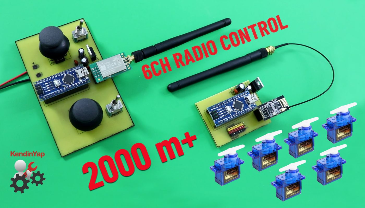
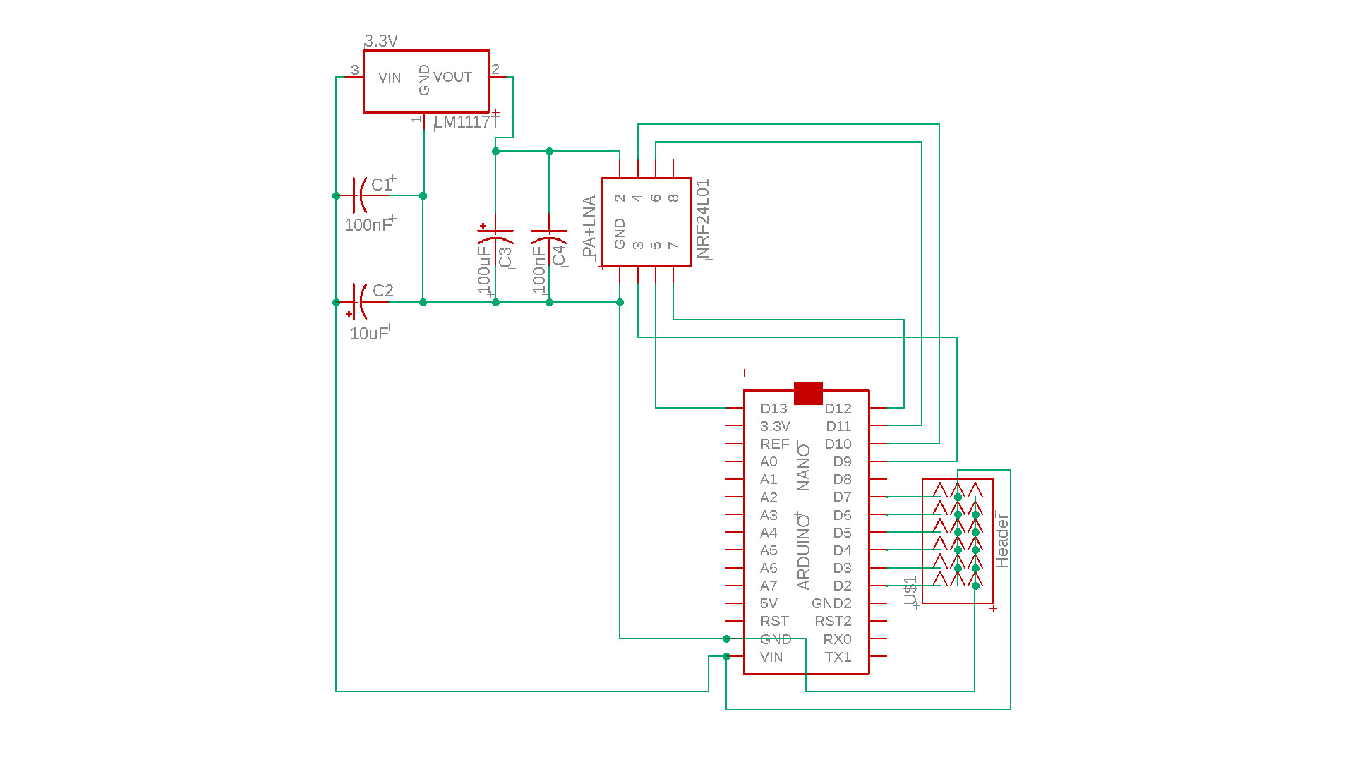
Making a 6-channel, long-range remote control with Arduino and 2.4Ghz NRF24L01 Modules.
With this 6-Channel remote control circuit, you can control model vehicles such as RC planes, RC cars, RC boats, RC work machines, RC tanks.
The maximum range of the remote control is over 2000 meters (1.24 miles+) under ideal conditions.
Materials required:
2 x PS4 Analogue Joystick (10K) : https://s.click.aliexpress.com/e/_DBSn2AB
2 x Toggle switch: https://s.click.aliexpress.com/e/_DCd5Pzh
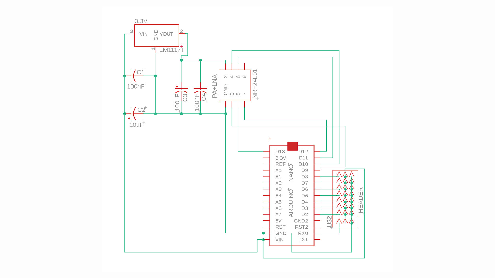
1 x NRF24L01+PA+LN 100mW (E01-ML01DP5): https://s.click.aliexpress.com/e/_DmEoWQf
(Optional: More long range version : https://s.click.aliexpress.com/e/_DeXGmgd)
1 x NRF24L01+PA+Wireless SMD: https://s.click.aliexpress.com/e/_DekKUm9
2 x Arduino Nano: https://s.click.aliexpress.com/e/_DlhwLS3
2 x 100uF (16V or above) electrolytic capacitors : https://s.click.aliexpress.com/e/_DBJpcn1
Female Header Pin (15 pins) 15P Female: https://s.click.aliexpress.com/e/_DDqmgbh
Universal PCB board: https://s.click.aliexpress.com/e/_DF8xNJ9
10uF electrolytic capacitors : https://s.click.aliexpress.com/e/_DDVm071
100uF electrolytic capacitors: https://s.click.aliexpress.com/e/_Ddfia2R
100nF (104) ceramic capacitor: https://s.click.aliexpress.com/e/_DmUGp7T
LM1117 3.3 Regulator IC: https://s.click.aliexpress.com/e/_DEpLIel
2×4 pin Header: https://s.click.aliexpress.com/e/_DdnClhn
80W soldering iron: https://s.click.aliexpress.com/e/_DmoQT1r
Digital Multimetre AC DC A830L : https://s.click.aliexpress.com/e/_DmjzgOJ
Digital Multimetre AC DC ANENG XL830L : https://s.click.aliexpress.com/e/_DEJiyIP
UT61 Professional Digital Multimeter Tester: https://s.click.aliexpress.com/e/_DmtkrmJ
AA Battery Box (5xAA Cells) 5 Slot: https://s.click.aliexpress.com/e/_DFMnduf
Heat-Shrink: https://s.click.aliexpress.com/e/_DnMQjEj
6-Channel Version GERBER & PDF FILES: https://drive.google.com/file/d/1nzZ1APkTlRCIaTYjvVbUQuV6dDC1I2WS/view?usp=sharing
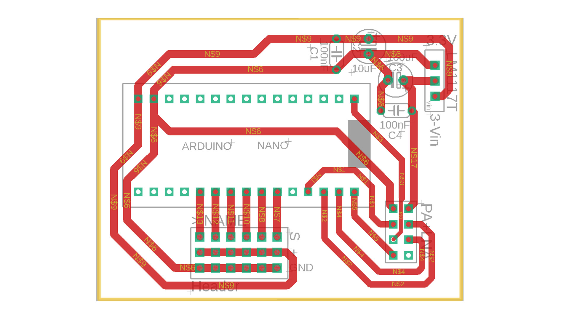
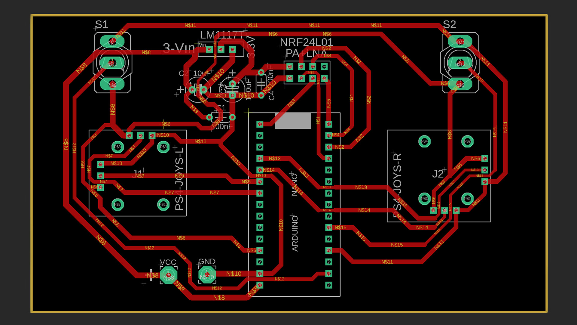
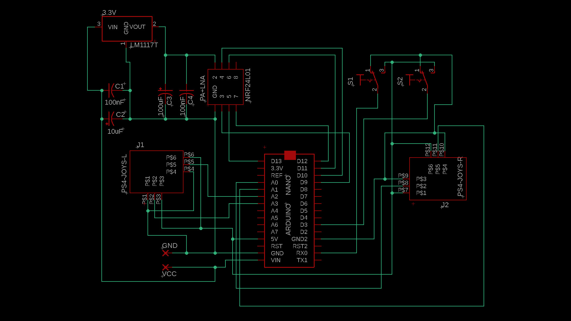
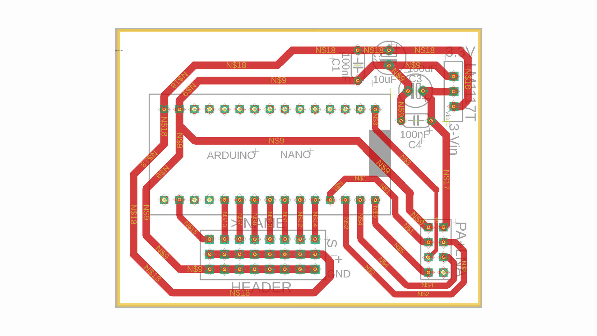
PCB Board Size:
Transmitter: 114 x 65mm
Receiver: 60 x 45mm
Transmitter and Receiver Codes Download: https://drive.google.com/file/d/1nv7hXkNy-fmLANADhOJTKW3Nz5aKS14R/view?usp=sharing
6-Channel Transmitter Code For Arduino Nano:
// 6 Channel Transmitter | 6 Kanal Verici
// KendinYap Channel

  #include <SPI.h>
  #include <nRF24L01.h>
  #include <RF24.h>
  const uint64_t pipeOut = 0xABCDABCD71LL;         // NOTE: The address in the Transmitter and Receiver code must be the same "0xABCDABCD71LL" | Verici ve Alıcı kodundaki adres aynı olmalıdır
  RF24 radio(9, 10);                               // select CE,CSN pin | CE ve CSN pinlerin seçimi

  struct Signal {
  byte throttle;
  byte pitch;
  byte roll;
  byte yaw;
  byte aux1;
  byte aux2;

};
  Signal data;
  void ResetData()
{
  data.throttle = 0;
  data.pitch = 127;
  data.roll = 127;
  data.yaw = 127;
  data.aux1 = 0;
  data.aux2 = 0;

}
  void setup()
{
                                       // Configure the NRF24 module  | NRF24 modül konfigürasyonu
  radio.begin();
  radio.openWritingPipe(pipeOut);
  radio.setChannel(100);
  radio.setAutoAck(false);
  radio.setDataRate(RF24_250KBPS);    // The lowest data rate value for more stable communication  | Daha kararlı iletişim için en düşük veri hızı.
  radio.setPALevel(RF24_PA_MAX);      // Output power is set for maximum range  |  Çıkış gücü maksimum menzil için ayarlanıyor.
  radio.stopListening();              // Start the radio comunication for Transmitter | Verici için sinyal iletişimini başlatır.
  ResetData();

}
                                      // Joystick center and its borders | Joystick merkez ve sınırları
  int Border_Map(int val, int lower, int middle, int upper, bool reverse)
{
  val = constrain(val, lower, upper);
  if ( val < middle )
  val = map(val, lower, middle, 0, 128);
  else
  val = map(val, middle, upper, 128, 255);
  return ( reverse ? 255 - val : val );
}
  void loop()
{

  data.roll = Border_Map( analogRead(A3), 0, 512, 1023, true );        // CH1   Note: "true" or "false" for signal direction | "true" veya "false" sinyal yönünü belirler
  data.pitch = Border_Map( analogRead(A0), 0, 512, 1023, true );       // CH2
  data.throttle = Border_Map( analogRead(A2),0, 340, 570, true );      // CH3   Note: For Single side ESC | Tek yönlü ESC için
  // data.throttle = Border_Map( analogRead(A2),0, 512, 1023, true );  // CH3   Note: For Bidirectional ESC | Çift yönlü ESC için
  data.yaw = Border_Map( analogRead(A1), 0, 512, 1023, false );        // CH4
  data.aux1 = digitalRead(0);                                          // CH5
  data.aux2 = digitalRead(3);                                          // CH6

  radio.write(&data, sizeof(Signal));
}
6-Channel Receiver Code For Arduino Nano:
//  6 Channel Receiver | 6 Kanal Alıcı

#include <SPI.h>
#include <nRF24L01.h>
#include <RF24.h>
#include <Servo.h>

int ch_width_1 = 0;
int ch_width_2 = 0;
int ch_width_3 = 0;
int ch_width_4 = 0;
int ch_width_5 = 0;
int ch_width_6 = 0;

Servo ch1;
Servo ch2;
Servo ch3;
Servo ch4;
Servo ch5;
Servo ch6;

struct Signal {

byte throttle;
byte pitch;
byte roll;
byte yaw;
byte aux1;
byte aux2;

};

Signal data;

const uint64_t pipeIn = 0xABCDABCD71LL;
RF24 radio(9, 10);

void ResetData()
{

data.throttle = 0;                                         // Define the inicial value of each data input. | Veri girişlerinin başlangıç değerleri
data.roll = 127;
data.pitch = 127;
data.yaw = 127;
data.aux1 = 0;
data.aux2 = 0;

}

void setup()
{
                                                           // Set the pins for each PWM signal | Her bir PWM sinyal için pinler belirleniyor.
  ch1.attach(2);
  ch2.attach(3);
  ch3.attach(4);
  ch4.attach(5);
  ch5.attach(6);
  ch6.attach(7);

  ResetData();                                             // Configure the NRF24 module  | NRF24 Modül konfigürasyonu
  radio.begin();
  radio.openReadingPipe(1,pipeIn);
  radio.setChannel(100);
  radio.setAutoAck(false);
  radio.setDataRate(RF24_250KBPS);                         // The lowest data rate value for more stable communication  | Daha kararlı iletişim için en düşük veri hızı.
  radio.setPALevel(RF24_PA_MAX);                           // Output power is set for maximum |  Çıkış gücü maksimum için ayarlanıyor.
  radio.startListening();                                  // Start the radio comunication for receiver | Alıcı için sinyal iletişimini başlatır.

}

unsigned long lastRecvTime = 0;

void recvData()
{
while ( radio.available() ) {
radio.read(&data, sizeof(Signal));
lastRecvTime = millis();                                    // Receive the data | Data alınıyor
}
}

void loop()
{
recvData();
unsigned long now = millis();
if ( now - lastRecvTime > 1000 ) {
ResetData();                                                // Signal lost.. Reset data | Sinyal kayıpsa data resetleniyor
}

ch_width_1 = map(data.roll, 0, 255, 1000, 2000);
ch_width_2 = map(data.pitch, 0, 255, 1000, 2000);
ch_width_3 = map(data.throttle, 0, 255, 1000, 2000);
ch_width_4 = map(data.yaw, 0, 255, 1000, 2000);
ch_width_5 = map(data.aux1, 0, 1, 1000, 2000);
ch_width_6 = map(data.aux2, 0, 1, 1000, 2000);

ch1.writeMicroseconds(ch_width_1);                          // Write the PWM signal | PWM sinyaller çıkışlara gönderiliyor
ch2.writeMicroseconds(ch_width_2);
ch3.writeMicroseconds(ch_width_3);
ch4.writeMicroseconds(ch_width_4);
ch5.writeMicroseconds(ch_width_5);
ch6.writeMicroseconds(ch_width_6);

}
_______________________________________
8-Channel Version Transmitter and Receiver
_______________________________________
8-Channel Version PDF and Gerber Files: https://drive.google.com/file/d/1Rkizn8hUWnudV3X0FFvIstjzWnkRgt7W/view?usp=sharing
PCB Board Size:
Transmitter: 122 x 75mm
Receiver: 60 x 45mm
Arduino Nano Code For 8-Channel Transmitter:
// 8 Channel Transmitter | 8 Kanal Verici
// KendinYap Channel

  #include <SPI.h>
  #include <nRF24L01.h>
  #include <RF24.h>
  const uint64_t pipeOut = 0xABCDABCD71LL;         // NOTE: The address in the Transmitter and Receiver code must be the same "0xABCDABCD71LL" | Verici ve Alıcı kodundaki adres aynı olmalıdır
  RF24 radio(9, 10);                               // select CE,CSN pins | CE ve CSN pinlerin seçimi

  struct Signal {
  byte throttle;
  byte pitch;
  byte roll;
  byte yaw;
  byte aux1;
  byte aux2;
  byte aux3;
  byte aux4;
};
  Signal data;
  void ResetData()
{
  data.throttle = 0;
  data.pitch = 127;
  data.roll = 127;
  data.yaw = 127;
  data.aux1 = 0;
  data.aux2 = 0;
  data.aux3 = 0;
  data.aux4 = 0;
}
  void setup()
{
                                       // Configure the NRF24 module  | NRF24 modül konfigürasyonu
  radio.begin();
  radio.openWritingPipe(pipeOut);
  radio.setChannel(100);
  radio.setAutoAck(false);
  radio.setDataRate(RF24_250KBPS);    // The lowest data rate value for more stable communication  | Daha kararlı iletişim için en düşük veri hızı.
  radio.setPALevel(RF24_PA_MAX);      // Output power is set for maximum range  |  Çıkış gücü maksimum menzil için ayarlanıyor.
  radio.stopListening();              // Start the radio comunication for Transmitter | Verici için sinyal iletişimini başlatır.
  ResetData();

}
                                      // Joystick center and its borders | Joystick merkez ve sınırları
  int Border_Map(int val, int lower, int middle, int upper, bool reverse)
{
  val = constrain(val, lower, upper);
  if ( val < middle )
  val = map(val, lower, middle, 0, 128);
  else
  val = map(val, middle, upper, 128, 255);
  return ( reverse ? 255 - val : val );
}
  void loop()
{

  data.roll = Border_Map( analogRead(A7), 0, 512, 1023, true );        // CH1   Note: "true" or "false" for signal direction | "true" veya "false" sinyal yönünü belirler
  data.pitch = Border_Map( analogRead(A6), 0, 512, 1023, true );       // CH2
  data.throttle = Border_Map( analogRead(A3),0, 570, 800, true );      // CH3   Note: For Single side ESC | Tek yönlü ESC için
  // data.throttle = Border_Map( analogRead(A3),0, 512, 1023, true );  // CH3   Note: For Bidirectional ESC | Çift yönlü ESC için
  data.yaw = Border_Map( analogRead(A4), 0, 512, 1023, false );        // CH4
  data.aux1 = digitalRead(0);                                          // CH5
  data.aux2 = digitalRead(3);                                          // CH6
  data.aux3 = Border_Map( analogRead(A0),0, 512, 1023, true );         // CH7
  data.aux4 = Border_Map( analogRead(A1),0, 512, 1023, true );         // CH8

  radio.write(&data, sizeof(Signal));
}
Arduino Nano Code For 8-Channel Receiver:
//  8-Channel Receiver | 8 Kanal Alıcı

#include <SPI.h>
#include <nRF24L01.h>
#include <RF24.h>
#include <Servo.h>

int ch_width_1 = 0;
int ch_width_2 = 0;
int ch_width_3 = 0;
int ch_width_4 = 0;
int ch_width_5 = 0;
int ch_width_6 = 0;

int ch_width_7 = 0;
int ch_width_8 = 0;

Servo ch1;
Servo ch2;
Servo ch3;
Servo ch4;
Servo ch5;
Servo ch6;

Servo ch7;
Servo ch8;

struct Signal {

byte throttle;
byte pitch;
byte roll;
byte yaw;
byte aux1;
byte aux2;

byte aux3;
byte aux4;

};

Signal data;

const uint64_t pipeIn = 0xABCDABCD71LL;
RF24 radio(9, 10);

void ResetData()
{

data.throttle = 0;                                         // Define the inicial value of each data input. | Veri girişlerinin başlangıç değerleri
data.roll = 127;
data.pitch = 127;
data.yaw = 127;
data.aux1 = 0;
data.aux2 = 0;

data.aux3 = 0;
data.aux4 = 0;

}

void setup()
{
                                                           // Set the pins for each PWM signal | Her bir PWM sinyal için pinler belirleniyor.
  ch1.attach(2);
  ch2.attach(3);
  ch3.attach(4);
  ch4.attach(5);
  ch5.attach(6);
  ch6.attach(7);

  ch7.attach(8);
  ch8.attach(0);

  ResetData();                                             // Configure the NRF24 module  | NRF24 Modül konfigürasyonu
  radio.begin();
  radio.openReadingPipe(1,pipeIn);
  radio.setChannel(100);
  radio.setAutoAck(false);
  radio.setDataRate(RF24_250KBPS);                         // The lowest data rate value for more stable communication  | Daha kararlı iletişim için en düşük veri hızı.
  radio.setPALevel(RF24_PA_MAX);                           // Output power is set for maximum |  Çıkış gücü maksimum için ayarlanıyor.
  radio.startListening();                                  // Start the radio comunication for receiver | Alıcı için sinyal iletişimini başlatır.

}

unsigned long lastRecvTime = 0;

void recvData()
{
while ( radio.available() ) {
radio.read(&data, sizeof(Signal));
lastRecvTime = millis();                                    // Receive the data | Data alınıyor
}
}

void loop()
{
recvData();
unsigned long now = millis();
if ( now - lastRecvTime > 1000 ) {
ResetData();                                                // Signal lost.. Reset data | Sinyal kayıpsa data resetleniyor
}

ch_width_1 = map(data.roll, 0, 255, 1000, 2000);
ch_width_2 = map(data.pitch, 0, 255, 1000, 2000);
ch_width_3 = map(data.throttle, 0, 255, 1000, 2000);
ch_width_4 = map(data.yaw, 0, 255, 1000, 2000);
ch_width_5 = map(data.aux1, 0, 1, 1000, 2000);
ch_width_6 = map(data.aux2, 0, 1, 1000, 2000);

ch_width_7 = map(data.aux3, 0, 255, 1000, 2000);
ch_width_8 = map(data.aux4, 0, 255, 1000, 2000);

ch1.writeMicroseconds(ch_width_1);                          // Write the PWM signal | PWM sinyaller çıkışlara gönderiliyor
ch2.writeMicroseconds(ch_width_2);
ch3.writeMicroseconds(ch_width_3);
ch4.writeMicroseconds(ch_width_4);
ch5.writeMicroseconds(ch_width_5);
ch6.writeMicroseconds(ch_width_6);

ch7.writeMicroseconds(ch_width_7);
ch8.writeMicroseconds(ch_width_8);

}
2 pieces of 10K potentiometers required for 8-channel transmitter: https://s.click.aliexpress.com/e/_DkbmbTR
The 7th and 8th channels are controlled with a potentiometer. It is necessary to fix the potentiometers vertically on the PCB with adhesive. You can bend the pins in an L shape. But since the pins are short, it will be necessary to extend them with a cable.
_______________________________________
If you like my projects and want to support me, my Patreon link is.. https://www.patreon.com/KNDYP
GENERAL INFO:
Before uploading the codes to Arduino, you need to download the necessary library files to your computer.
If there are no library files, the installation will not occur and an error will occur.
NRF24 Module Library File Links for download …..:
Required library file:
SPI.h
nRF24L01.h
RF24.h
Servo.h
NRF24 Module library Files (Github page): https://github.com/nRF24/RF24
NRF24 Module library File (zip) : https://github.com/nRF24/RF24/archive/master.zip
Servo Library: https://www.arduinolibraries.info/libraries/servo
How to install Arduino IDE? & How to install Library File?