01/20/2026

Arduino & NRF24 RC Circuit problems ​

What are the possible malfunction problems of remote control circuits made with Arduino and NRF24L01 modules, and how can they be solved?
First of all, you must make sure that you have assembled the circuit correctly and completely. If you are sure of this, the following topics may be useful for your solution.

Usually, the problem is caused by the NRF24L01 modules not being able to connect with each other.
These modules are negatively affected by electrical noise. And this creates problems with connection.

Things to consider to reduce electrical noise (interference):

The cables you use to assemble electronic components should be as short as possible. Excessively long cables increase electrical noise.
The wiring between the Arduino and the NRF24 module is important. It will be useful to twist the GND, CE and CSN cables together to reduce noise.


The ideal
is to create the circuit on a PCB. For circuits made by cable soldering, the risk of noise is high and connection problems are more common.

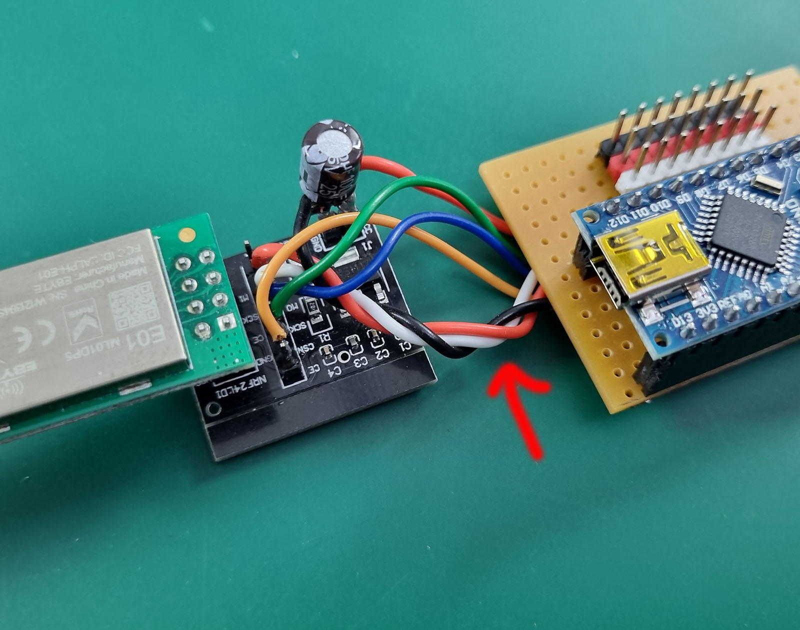
It is very important that the NRF24 module is supplied with stable and correct voltage. These modules operate with 3.3V. Arduino’s 3.3V pin output does not provide sufficient current power. Therefore, it is necessary to apply the following solutions;
An external NRF24 adapter module can be used. This module is a voltage regulator (Not a range extender). It ensures stable and sufficient power reaches the NRF24 module. Off-the-shelf NRF24 power modules can be used, or you can add an internal voltage regulator circuit to your circuit. Both do the same task.

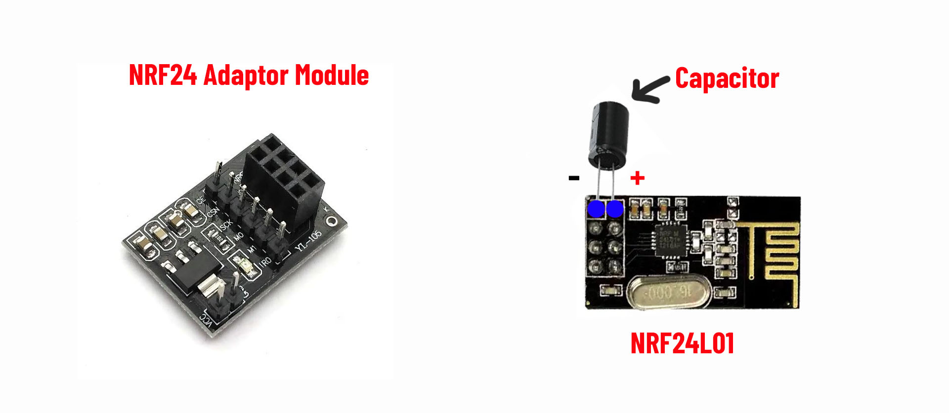
Another option is to solder an electrolytic capacitor to the positive and negative pins of the NRF24 module. Usually 10uf to 100uF (16V or above) is sufficient. Even if NRF24 modules are used with the adapter module produced for them, it may be useful to solder a capacitor to the positive and negative pins of NRF24.


The batteries
you use to power the circuits are also important. For example, 9V batteries are not suitable for NRF24 modules. They are inefficient because their current power is very low. And they can cause connection problems.

7.4V LiPo or Li-ion batteries or quality AA batteries (5xAA or 6XAA) should be used for the transmitter. Insufficient power supply may cause no connection to be established.
If the BEC of the ESC will not be used for the receiver, a good 5.5-6V power supply should be used. Otherwise, the circuit will not work or will cause very delayed and slow signal transmission. If the servos react too slowly, there is not enough power for the receiver.

Environmental impacts; Connection problems can sometimes be external. Devices operating with 2.4Ghz frequency in your area may cause noise and prevent the connection from being established. It may be necessary to try running it in a different location.

Adding the following line to your code to change the frequency subchannel may help resolve connection issues
radio.setChannel(VALUE) ;   The value here can be between 0 and 125. For example, a value of 90 causes the frequency of 2.4Ghz to become 2.49Ghz.
The frequency range can be minimum 2.4Ghz and maximum 2.525Ghz. This change can help you get rid of the frequencies around you that negatively affect your circuit.
This line of code must be added to both the transmitter and receiver code.

EXAMPLE;

radio.begin();
radio.openWritingPipe(pipeOut);
radio.setChannel(90); (New command line to add)

Connection problems can sometimes be caused by detuning; a poor antenna match. If the antenna matches when you hold the metal mounting part with two fingers, the problem is a poor antenna match. An indirect solution to this problem is to wrap the antenna in aluminum foil. This can ensure a constant connection. However, this solution only indirectly bypasses the problem. To solve the real problem, you should check the following points and take the necessary actions.

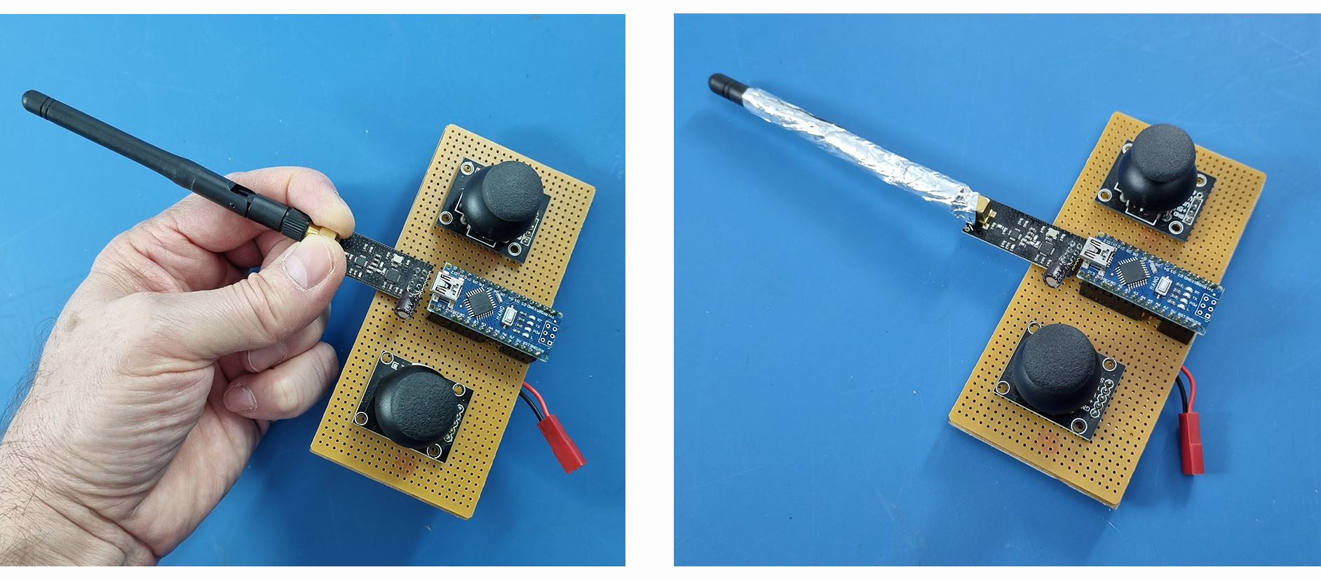
Main reasons for connection failure and solutions:

Power supply/noise issue:
nRF24L01 modules are integrated circuits that require clean and instantaneous current on a 3.3V line (TX instantaneous ~12–15 mA; instantaneous 100 mA+ in PA+LNA models). Powering from the Arduino’s 3.3V pin (especially UNO/Nano) is often insufficient; noise on the line significantly reduces receiver/transmitter sensitivity. Hand/foil effect: When you touch the antenna, your body acts like a “ground plane,” changing the antenna’s matching and radiation pattern; it also temporarily improves the SNR according to ambient noise. Aluminum foil also acts as a reflector/ground plane. Therefore, the real problem is masked, not the root cause.

Antenna/placement (RF matching) and environmental influence:
Matching will be disrupted if the module’s antenna area is near metal, cable bundles, or a breadboard, or if the antenna is unsuitable (incorrect cut length, poor soldering). Your body/foil antenna might be “detuning” and accidentally moving it to a better spot.


Quick Diagnostics/Solution List

Power and Filtering
Fuel the transmitter with a separate 3.3V regulator (at least 150–300 mA capacity, short cable).
Place a 100 nF + 10–47 µF capacitor as close as possible to the module’s VCC–GND (both).
Common GNDs; avoid long, thin Dupont cables.

Leveling and Connections

nRF24L01 only operates with 3.3V. Do not supply 5V to VCC. The nRF module must be supplied with a very stable, constant 3.3V.
Keep SPI lines short. Supply 3.3V leveling to CE/CSN/SCK/MOSI (level converter or simple divider if necessary).
Measure the continuity of CE/CSN pin assignments and cables; reversed/loose cables are common.

RF Placement and Antenna

Leave the antenna side of the module clear; do not place metal parts, batteries, or large copper fillers underneath/beside it.
If using an external antenna, ensure it is compatible with 2.4 GHz; check the SMA/u.FL solder joints.
Do not stand too close to devices; test at a distance of 0.5–2 m (in some cases, receiver saturation may occur at excessive proximity).

Software/Settings
Ensure both sides have the same channel, address, data rate, and CRC settings.
Set the data rate to 250 kbps in the first test (for better sensitivity).
Set the channel to a value far from Wi-Fi (e.g., try around channel 76).
Enable auto repeat and ACK settings; test with the GettingStarted and scanner examples of the RF24 (TMRh20) library.
In the first test, set the PA level to Low and see if it works, then gradually increase it (especially if using PA+LNA).

Module Quality

Some very cheap “mini” green cards can be faulty/unstable. Cross-test with a different module (standard, not PA+LNA if possible).


NRF24L01 modules have versions with different power:

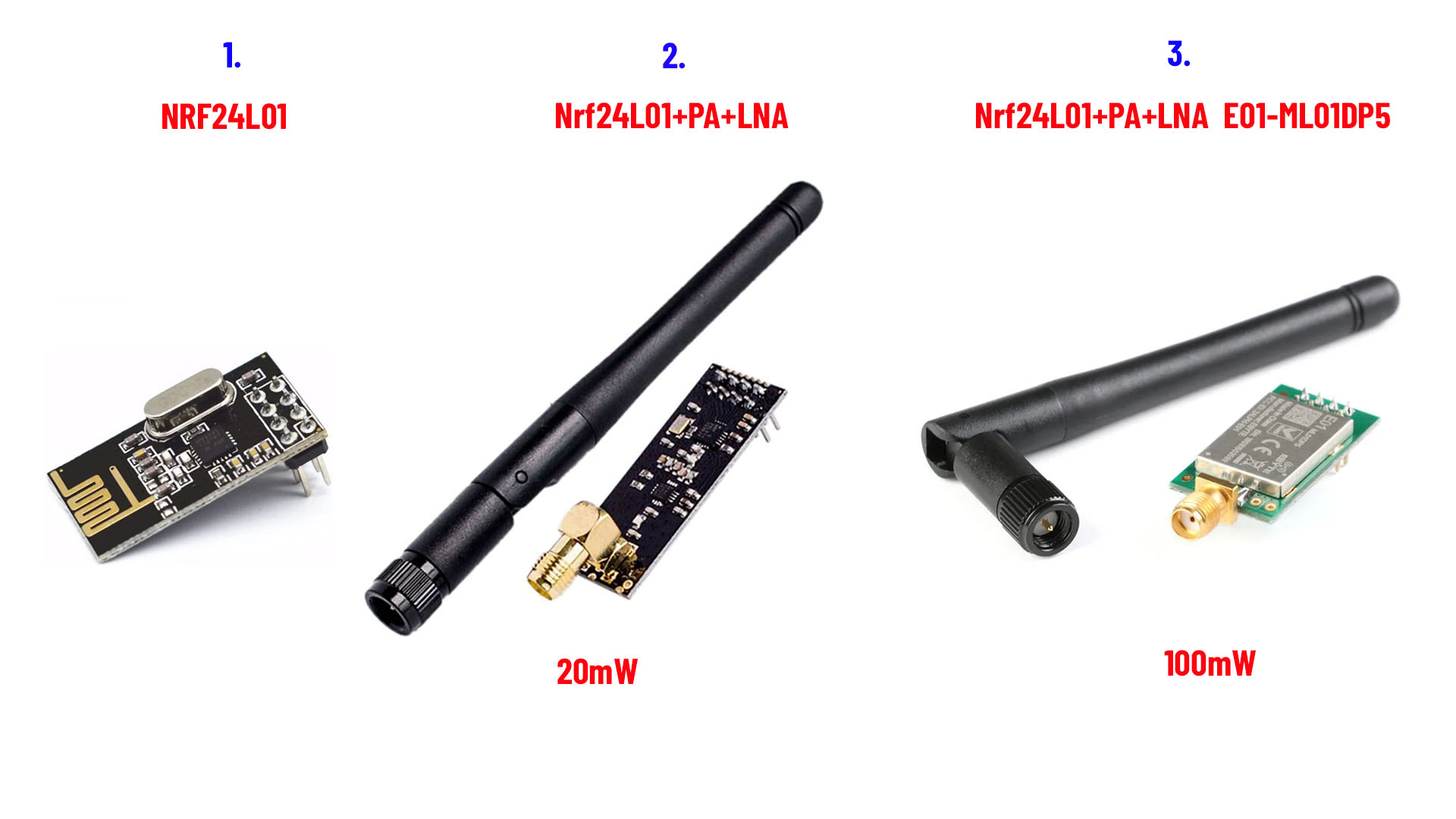
1. This version is very weak. Its range is very short and there are more connection problems. (The stable range I achieved in my tests is approximately 70-80 meters from Ground to Air)
2. This version (with Antenna) is more powerful. Its range is much longer. (The stable range I achieved in my tests is approximately 130-160 meters from Ground to Air)
3. This version is much more powerful and has a longer range. And its metal case acts as a filter. It is much less affected by noise. In this way, connection problems are rarely experienced.
(The stable range I achieved  in my tests is 2000 meters + from Ground to Air)

NOTE: If your circuit still does not work even though you have implemented all of these correctly and completely, one of the NRF24 modules you have may be defective. This possibility should also be considered.