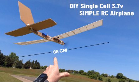
Fully 3D printed remote control model car, including gearbox, tires and rims.
Controlled by handmade RC. It can also be used with different RCs if desired.
I designed this model car to be low-cost and suitable for cheap motors and ESCs.
The Brushed 380 motor I use is a very cheap version. 380 motors are available with many different powers. You can use them for higher speed and torque.
Technicial Specifications:
Lenght: 392mm
Width: 165 mm
Ground clearance: 30mm
Wheelbase: 260mm
Weight: 940 gr
Required PLA filament: 565 gr
Required: TPU filament: 115 gr
Needs:
20A ESC: https://s.click.aliexpress.com/e/_DFglCoP
380 Brushed motor: https://s.click.aliexpress.com/e/_DkWjtUf
Power Led Lens (45-90°): https://s.click.aliexpress.com/e/_DeHGNCP
10x15x4 Ball Bearing 6700ZZ (10 pcs): https://s.click.aliexpress.com/e/_DFbcNRd
Mini Servo: https://s.click.aliexpress.com/e/_DkXpTK7
1W Power Led: https://s.click.aliexpress.com/e/_DCOiAOX
5.6R resistor: https://s.click.aliexpress.com/e/_DBMnLOx
1K Resistor: https://s.click.aliexpress.com/e/_DC0mHS3
BD139 Transistor: https://s.click.aliexpress.com/e/_DDsaVqx
PCB: https://s.click.aliexpress.com/e/_DdICY2J
2 Pin JST connector and cable (Male & Female): https://s.click.aliexpress.com/e/_DETIA4b
18650 Battery Box: https://s.click.aliexpress.com/e/_Dlwva2J
18650 Battery (2 pcs): https://s.click.aliexpress.com/e/_DlrahcJ
M2.2 or M2.3mm screws: https://s.click.aliexpress.com/e/_Dkj7J3V
M2x14mm screw: https://s.click.aliexpress.com/e/_Dm2HitN
M2x75mm rod: https://s.click.aliexpress.com/e/_DDlLTtv
Screw List:
M2.2×6.5 mm (6 pcs)
M2.2×9.5 mm (22 pcs)
M2.2×13 mm (27 pcs)
M2.2×16 mm 822 pcs)
M3x25 mm (1 pcs)
M2x8mm (2 pcs)
M2x14 mm (2 pcs)
3D STL Files: https://www.printables.com/model/879237-fully-3d-printed-rc-pick-up
This handmade remote control has 6 channels. We only need 3 channels for pickup. One channel for steering control, one channel for forward-reverse and speed control, and one channel for turning the headlights on and off. The other 3 channels will remain idle.
Electronic switch circuit to control head lights:
In order to use the light switch circuit, we need to make a small addition to the receiver code.
“if (ch_width_6>1400) digitalWrite(8, HIGH); else digitalWrite(8, LOW);”
This code allows us to control the lights via channel 6.
The transistor connected to the D8 pin of the receiver is used as an electronic switch.
The full receiver code with this line added is below.
//  6 Channel Receiver & Transistor Control | 6 Kanal Alıcı ve Transistor Kontrol
// KendinYap Channel

#include <SPI.h>
#include <nRF24L01.h>
#include <RF24.h>
#include <Servo.h>

int ch_width_1 = 0;
int ch_width_2 = 0;
int ch_width_3 = 0;
int ch_width_4 = 0;
int ch_width_5 = 0;
int ch_width_6 = 0;

Servo ch1;
Servo ch2;
Servo ch3;
Servo ch4;
Servo ch5;
Servo ch6;

struct Signal {

byte throttle;
byte pitch;
byte roll;
byte yaw;
byte aux1;
byte aux2;

};

Signal data;

const uint64_t pipeIn = 0xABCDABCD71LL;
RF24 radio(9, 10);

void ResetData()
{

data.throttle = 127;                                         // Define the inicial value of each data input. | Veri girişlerinin başlangıç değerleri
data.roll = 127;
data.pitch = 127;
data.yaw = 127;
data.aux1 = 0;
data.aux2 = 0;

}

void setup()
{
  pinMode(8, OUTPUT);                                      // Arduino Nano Pin 8 i çıkış pini olarak tanımlama

  ch1.attach(2);                                           // Set the pins for each PWM signal | Her bir PWM sinyal için pinler belirleniyor.
  ch2.attach(3);
  ch3.attach(4);
  ch4.attach(5);
  ch5.attach(6);
  ch6.attach(7);

  ResetData();                                             // Configure the NRF24 module  | NRF24 Modül konfigürasyonu
  radio.begin();
  radio.openReadingPipe(1,pipeIn);
  radio.setChannel(100);
  radio.setAutoAck(false);
  radio.setDataRate(RF24_250KBPS);                         // The lowest data rate value for more stable communication  | Daha kararlı iletişim için en düşük veri hızı.
  radio.setPALevel(RF24_PA_MAX);                           // Output power is set for maximum |  Çıkış gücü maksimum için ayarlanıyor.
  radio.startListening();                                  // Start the radio comunication for receiver | Alıcı için sinyal iletişimini başlatır.

}

unsigned long lastRecvTime = 0;

void recvData()
{
while ( radio.available() ) {
radio.read(&data, sizeof(Signal));
lastRecvTime = millis();                                    // Receive the data | Data alınıyor
}
}

void loop()
{
recvData();
unsigned long now = millis();
if ( now - lastRecvTime > 1000 ) {
ResetData();                                                // Signal lost.. Reset data | Sinyal kayıpsa data resetleniyor

}

ch_width_1 = map(data.roll, 0, 255, 1000, 2000);
ch_width_2 = map(data.pitch, 0, 255, 1000, 2000);
ch_width_3 = map(data.throttle, 0, 255, 1000, 2000);
ch_width_4 = map(data.yaw, 0, 255, 1000, 2000);
ch_width_5 = map(data.aux1, 0, 1, 1000, 2000);
ch_width_6 = map(data.aux2, 0, 1, 1000, 2000);

if (ch_width_6>1400) digitalWrite(8, HIGH); else digitalWrite(8, LOW);      // It controls the transistor connected to the 8th pin of Arduino Nano.  | Arduino Nano nun 8. pinine bağlı olan transistörü kontrol eder

ch1.writeMicroseconds(ch_width_1);                          // Write the PWM signal | PWM sinyaller çıkışlara gönderiliyor
ch2.writeMicroseconds(ch_width_2);
ch3.writeMicroseconds(ch_width_3);
ch4.writeMicroseconds(ch_width_4);
ch5.writeMicroseconds(ch_width_5);
ch6.writeMicroseconds(ch_width_6);

}


