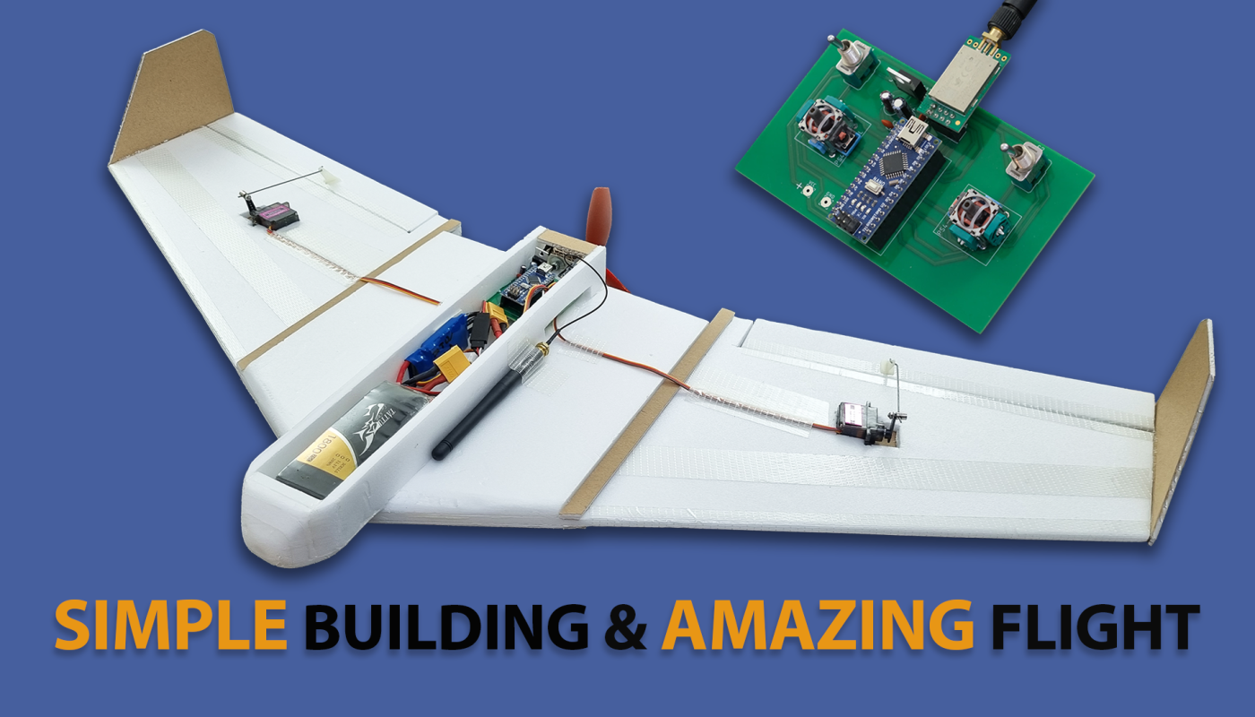
You can build a very stable flying-wing model using simple materials. It’s simple, but it flies beautifully.
You can also make the necessary remote control yourself. Below you’ll find the necessary material links, code, and Gerber files for the remote control circuit featuring a V-tail mix.
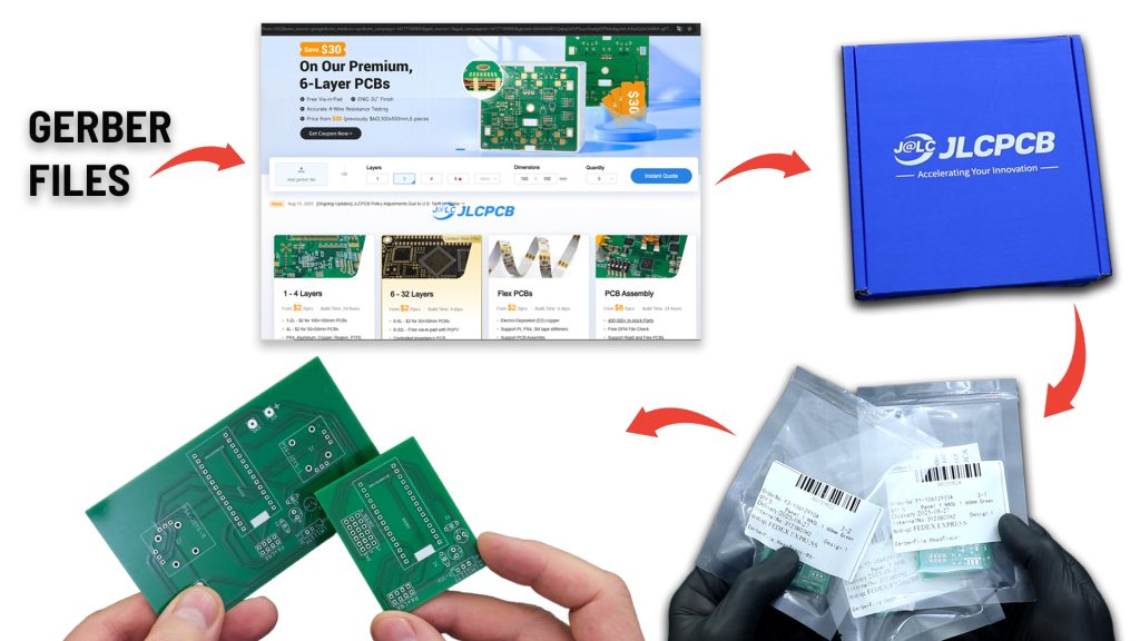
For this model, I designed a remote control with a V-tail mix. I needed PCBs for the transmitter and receiver circuits I designed. I chose JLCPCB again for PCB fabrication.
After placing my order, my PCBs were prepared and shipped within 24 hours. They arrived 5-6 days later.
The PCBs are truly high-quality, just like the ones I received with my previous order.
I thank JLCPCB for their high quality and fast service.
You can reach JLCPCB through the affiliate link below.
Discover Easy, Affordable, and Reliable PCB Manufacturing with JLCPCB! Register to receive a $70 New Customer Coupon: https://jlcpcb.com/?from=KendinYap
Dimension diagrams:
Needs:
2205 2300KB Motor (CW): https://s.click.aliexpress.com/e/_c4nRBtf5
30A BL ESC : https://s.click.aliexpress.com/e/_c3VUiwVV
5050 or 5045 3-Blade Propeller: https://s.click.aliexpress.com/e/_c4OTvBET
MG90S Servo : https://s.click.aliexpress.com/e/_c3DsOBcn
NRF24L01+PA+LN 100mW (E01-ML01DP5): https://s.click.aliexpress.com/e/_DmEoWQf
Arduino Nano V3 (Micro connector): https://s.click.aliexpress.com/e/_c3b9RuoL
GT-24 NRF24L01+PA+LNA (With Antenna): https://s.click.aliexpress.com/e/_DekKUm9
2 x PS4 Analogue Joystick (10K) : https://s.click.aliexpress.com/e/_c4rwcFkn OR https://s.click.aliexpress.com/e/_o2DDPGN
2 x Toggle switch: https://s.click.aliexpress.com/e/_DCd5Pzh
LM1117 3.3V: https://s.click.aliexpress.com/e/_c3HKkBAT
Capacitors 10uF (2 pcs), 100uF (3 pcs): https://s.click.aliexpress.com/e/_c3CX0WUb
Capacitor 100nF 104 (5 pcs): https://s.click.aliexpress.com/e/_omwl5j1
JST 2-Pin : https://s.click.aliexpress.com/e/_ooekDr1
6mm insulation styrofoam (2 plate)
3mm kraft foamboard (1 plate)
80W soldering iron: https://s.click.aliexpress.com/e/_c4KNZUMT
Digital Multimetre AC DC A830L : https://s.click.aliexpress.com/e/_c4PlUhET
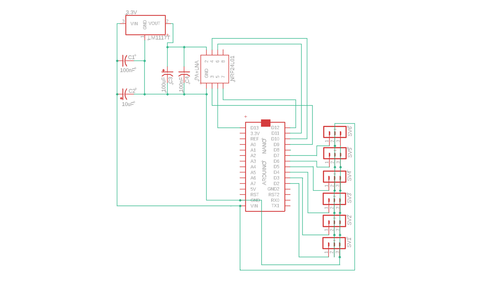
Transmitter Schematic:
The remote control circuit has six channels. However, three channels will be used for the Flying-Wing model. Elevator, aileron and throttle controls are sufficient for this type of model.
Transmitter Code For Arduino NANO :
					// 6 Channel Transmitter | 6 Kanal Verici
// @KendinYap Channel

  #include <SPI.h>
  #include <nRF24L01.h>
  #include <RF24.h>
  const uint64_t pipeOut = 0xABCDABCD71LL;         // NOTE: The address in the Transmitter and Receiver code must be the same "0xABCDABCD71LL" | Verici ve Alıcı kodundaki adres aynı olmalıdır
  RF24 radio(9, 10);                               // select CE,CSN pin | CE ve CSN pinlerin seçimi

  struct Signal {
  byte throttle;
  byte pitch;
  byte roll;
  byte yaw;
  byte aux1;
  byte aux2;

};
  Signal data;
  void ResetData()
{
  data.throttle = 0;
  data.pitch = 127;
  data.roll = 127;
  data.yaw = 127;
  data.aux1 = 0;
  data.aux2 = 0;

}
  void setup()
{
                                       // Configure the NRF24 module  | NRF24 modül konfigürasyonu
  radio.begin();
  radio.openWritingPipe(pipeOut);
  radio.setChannel(100);
  radio.setAutoAck(false);
  radio.setDataRate(RF24_250KBPS);    // The lowest data rate value for more stable communication  | Daha kararlı iletişim için en düşük veri hızı.
  radio.setPALevel(RF24_PA_MAX);      // Output power is set for maximum range  |  Çıkış gücü maksimum menzil için ayarlanıyor.
  radio.stopListening();              // Start the radio comunication for Transmitter | Verici için sinyal iletişimini başlatır.
  ResetData();

}
                                      // Joystick center and its borders | Joystick merkez ve sınırları
  int Border_Map(int val, int lower, int middle, int upper, bool reverse)
{
  val = constrain(val, lower, upper);
  if ( val < middle )
  val = map(val, lower, middle, 0, 128);
  else
  val = map(val, middle, upper, 128, 255);
  return ( reverse ? 255 - val : val );
}
  void loop()
{

  data.roll = Border_Map( analogRead(A3), 0, 512, 1023, true );        // CH1   Note: "true" or "false" for signal direction | "true" veya "false" sinyal yönünü belirler
  data.pitch = Border_Map( analogRead(A0), 0, 512, 1023, true );       // CH2
  data.throttle = Border_Map( analogRead(A2),0, 340, 570, true );      // CH3   Note: For Single side ESC | Tek yönlü ESC için
  // data.throttle = Border_Map( analogRead(A2),0, 512, 1023, true );  // CH3   Note: For Bidirectional ESC | Çift yönlü ESC için
  data.yaw = Border_Map( analogRead(A1), 0, 512, 1023, false );        // CH4
  data.aux1 = digitalRead(0);                                          // CH5
  data.aux2 = digitalRead(3);                                          // CH6

  radio.write(&data, sizeof(Signal));
}
Receiver Code For Arduino (V-Tail Mix) :
					//  6 Channel Receiver | 6 Kanal Alıcı
// KendinYap Channel

#include <SPI.h>
#include <nRF24L01.h>
#include <RF24.h>
#include <Servo.h>

int ch_width_1 = 0;
int ch_width_2 = 0;
int ch_width_3 = 0;
int ch_width_4 = 0;
int ch_width_5 = 0;
int ch_width_6 = 0;

Servo ch1;
Servo ch2;
Servo ch3;
Servo ch4;
Servo ch5;
Servo ch6;

struct Signal {

byte throttle;
byte pitch;
byte roll;
byte yaw;
byte aux1;
byte aux2;

};

Signal data;

const uint64_t pipeIn = 0xABCDABCD71LL;
RF24 radio(9, 10);

void ResetData()
{

data.throttle = 0;                                         // Define the inicial value of each data input. | Veri girişlerinin başlangıç değerleri
data.roll = 127;
data.pitch = 127;
data.yaw = 127;
data.aux1 = 0;
data.aux2 = 0;

}

void setup()
{
                                                           // Set the pins for each PWM signal | Her bir PWM sinyal için pinler belirleniyor.
  ch1.attach(2);
  ch2.attach(3);
  ch3.attach(4);
  ch4.attach(5);
  ch5.attach(6);
  ch6.attach(7);

  ResetData();                                             // Configure the NRF24 module  | NRF24 Modül konfigürasyonu
  radio.begin();
  radio.openReadingPipe(1,pipeIn);
  radio.setChannel(100);
  radio.setAutoAck(false);
  radio.setDataRate(RF24_250KBPS);                         // The lowest data rate value for more stable communication  | Daha kararlı iletişim için en düşük veri hızı.
  radio.setPALevel(RF24_PA_MAX);                           // Output power is set for maximum |  Çıkış gücü maksimum için ayarlanıyor.
  radio.startListening();                                  // Start the radio comunication for receiver | Alıcı için sinyal iletişimini başlatır.

}

unsigned long lastRecvTime = 0;

void recvData()
{
while ( radio.available() ) {
radio.read(&data, sizeof(Signal));
lastRecvTime = millis();                                    // Receive the data | Data alınıyor
}
}

void loop()
{
recvData();
unsigned long now = millis();
if ( now - lastRecvTime > 1000 ) {
ResetData();                                                // Signal lost.. Reset data | Sinyal kayıpsa data resetleniyor
}

ch_width_1 = map(data.roll, 0, 255, 1000, 2000);
ch_width_2 = map(data.pitch, 0, 255, 1000, 2000);
ch_width_3 = map(data.throttle, 0, 255, 1000, 2000);
ch_width_4 = map(data.yaw, 0, 255, 1000, 2000);
ch_width_5 = map(data.aux1, 0, 1, 1000, 2000);
ch_width_6 = map(data.aux2, 0, 1, 1000, 2000);

ch1.writeMicroseconds(ch_width_1);                          // Write the PWM signal | PWM sinyaller çıkışlara gönderiliyor
ch2.writeMicroseconds(ch_width_2);
ch3.writeMicroseconds(ch_width_3);
ch4.writeMicroseconds(ch_width_4);
ch5.writeMicroseconds(ch_width_5);
ch6.writeMicroseconds(ch_width_6);

}
Transmitter and Receiver PCB GERBER Files: https://drive.google.com/file/d/1nzZ1APkTlRCIaTYjvVbUQuV6dDC1I2WS/view
GENERAL INFO:
Before uploading the codes to Arduino, you need to download the necessary library files to your computer.
If there are no library files, the installation will not occur and an error will occur.
NRF24 Module Library File Links for download …..:
Required library file:
SPI.h
nRF24L01.h
RF24.h
Servo.h
NRF24 Module library Files (Github page): https://github.com/nRF24/RF24
NRF24 Module library File (zip) : https://github.com/nRF24/RF24/archive/master.zip
Servo Library: https://www.arduinolibraries.info/libraries/servo