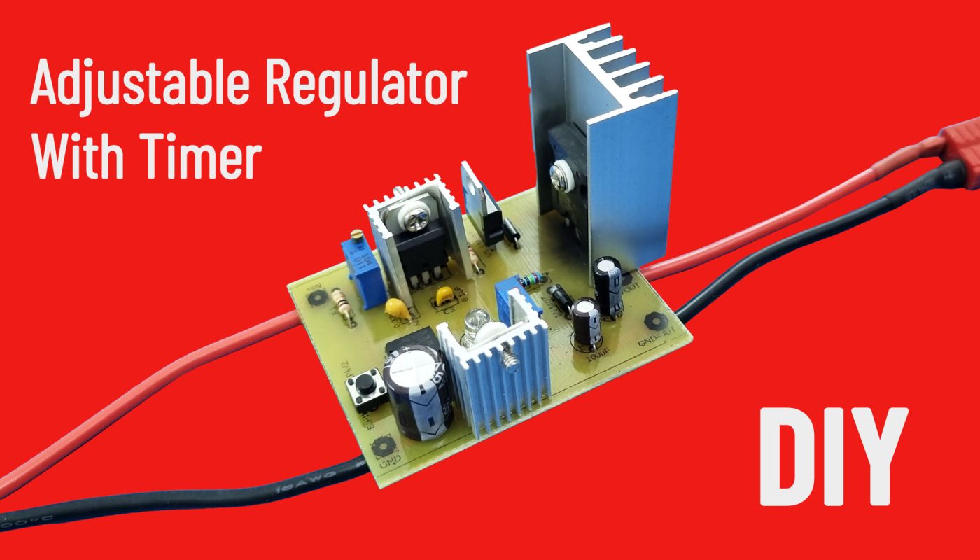
Timer and Voltage adjustable DC-DC voltage regulator circuit. Max 33V & Max 5A (90W)
This circuit is an adjustable voltage regulator. And it can be set to work for a certain time.
The ideal input voltage is 12-16V range. It has a maximum 35V input support. Its maximum power is 90W.
Output voltage range is 1.25-33V.
When the input voltage is lower than 16V, there is no overheating problem. (Of course, the load connected to the circuit should not draw more than 5A.)
If it will be supplied with an input voltage higher than 16V, the TIP35 must be cooled by a fan.
Resistors: https://s.click.aliexpress.com/e/_DdcnCxd
Capacitors (1uF, 10uF, 470uF): https://s.click.aliexpress.com/e/_DEyLDmX
Capacitors (0.1uF/100nf, 0.33uF/330nF): https://s.click.aliexpress.com/e/_Dknpqxl
Diodes: https://s.click.aliexpress.com/e/_DeMCDjv
NE555 IC: https://s.click.aliexpress.com/e/_DeMCDjv
Trimpot (5K, 100K): https://s.click.aliexpress.com/e/_DF7rXyx
7809: https://s.click.aliexpress.com/e/_DnKSjXD
LM317: https://s.click.aliexpress.com/e/_DFHimKj
5mm LED: https://s.click.aliexpress.com/e/_DFxp6l1
Tactile push button (6x6x5): https://s.click.aliexpress.com/e/_DBh8dAf
TIP35C: https://s.click.aliexpress.com/e/_DEBvylt
Heatsink (To 220): https://s.click.aliexpress.com/e/_DkC3Ry7
Heatsink (to 247): https://s.click.aliexpress.com/e/_DkJWxin
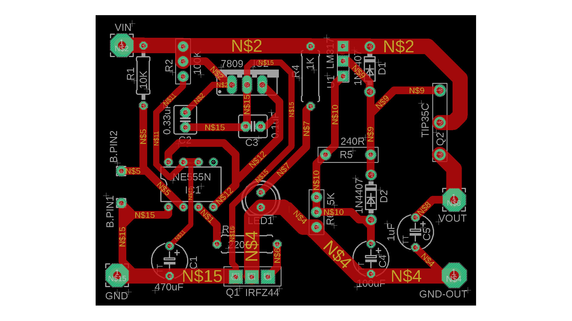
Single Side Copper PCB: https://s.click.aliexpress.com/e/_DD2XNgx
Heat-Shrink: https://s.click.aliexpress.com/e/_DnMQjEj
Mini Drill Bits: https://s.click.aliexpress.com/e/_DBZ9sTH
80W soldering iron: https://s.click.aliexpress.com/e/_DD75tWX
Digital Multimetre AC DC A830L : https://s.click.aliexpress.com/e/_DmjzgOJ
Digital Multimetre AC DC ANENG XL830L : https://s.click.aliexpress.com/e/_DEJiyIP
UT61 Profesyonel Digital Multimetre Tester: https://s.click.aliexpress.com/e/_DmtkrmJ
CIRCUIT PDF FILES: https://drive.google.com/file/d/1xaTDrzANUYdenJGogpIbCZ_-u01ftjTL/view?usp=sharing
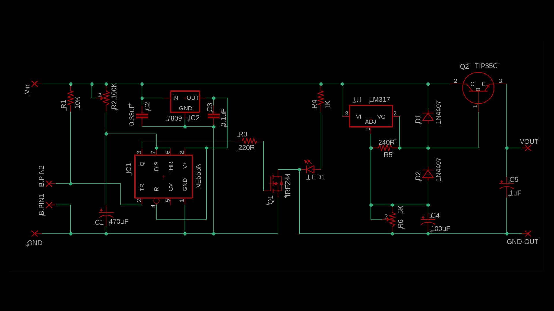
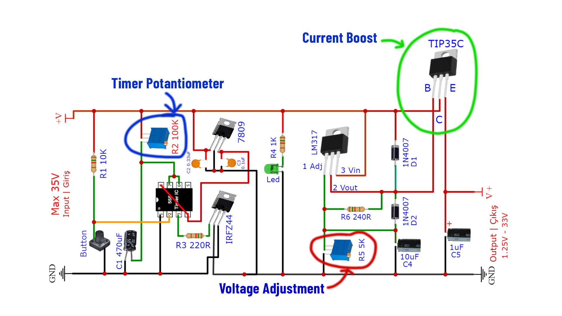
The voltage regulator circuit consists of two parts. The first part allows us to set the duration.
Factors determining the duration:
1-) 100K trimpot: When we increase the Ohm value, the working time increases. It decreases when we lower the value. If we need much longer time, 500K Trimpot can be used instead of 100K.
2-) C1 capacitor: A 470uF capacitor was used in the circuit. Using one with a higher value will increase the maximum time we can set. So if we use 1000uF instead of 470uF, the time we can set the maximum will be doubled.
3-) Input voltage: Input voltage has an inversely proportional effect. The lower input voltage provides a greater operating range in terms of duration. Optionally, if the timer circuit is fed from the constant voltage of the 7809, the input voltage will not affect the time.
Time Formula: T=1.1 x R2 x C1
The 555 IC used in the timer section can work with a maximum of 16V. If the circuit is fed with a higher input voltage, the 555 IC will break. 7809 Regulator was used to supply it with constant 9V. If desired, 7808 or 7812 can also be used.
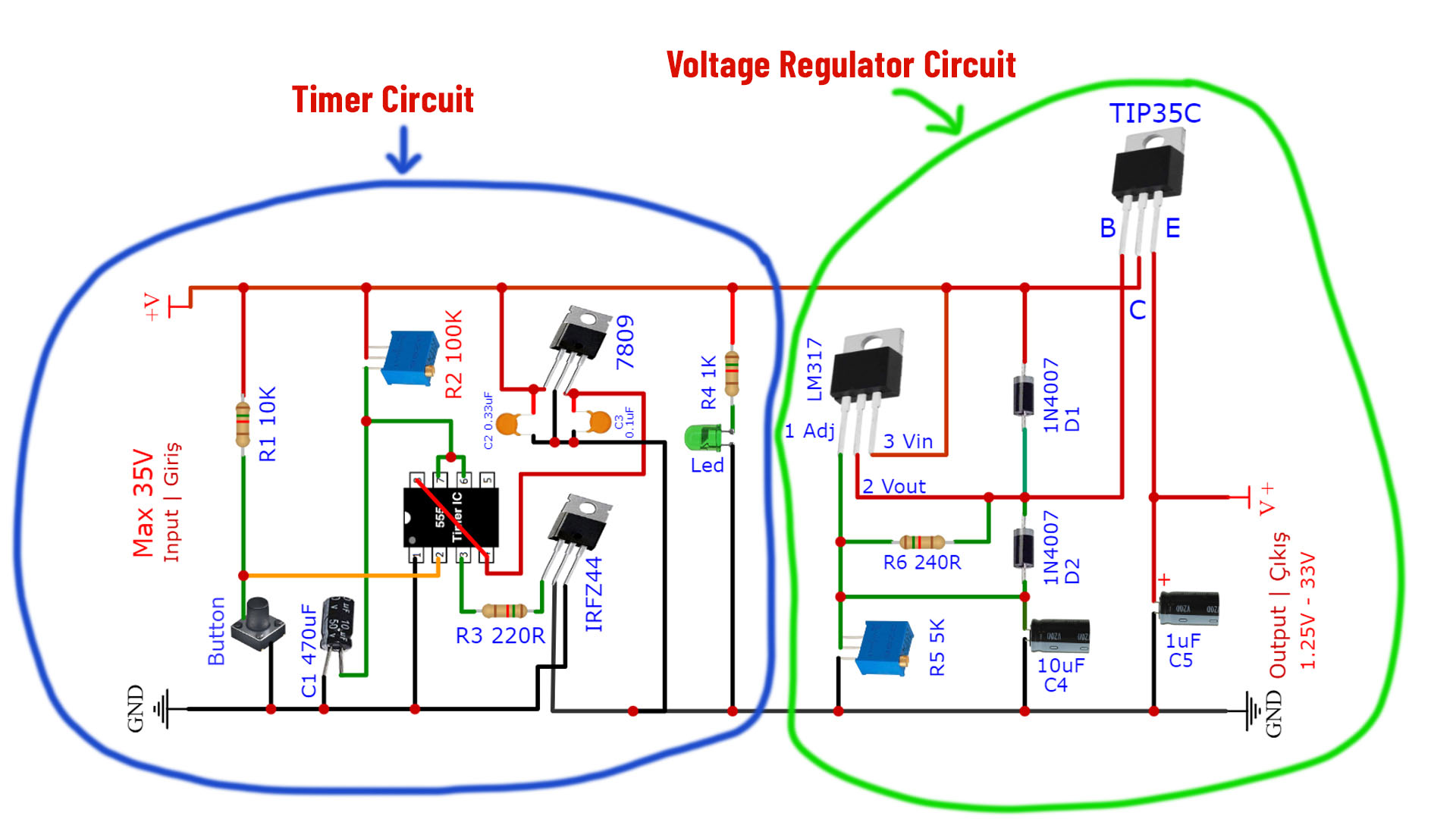
The second part is the adjustable voltage regulator. The voltage regulator is active during the time we set with the timer circuit. The timer circuit turns on/off with the IRFZ44 transistor.
LM317 regulator was used for voltage adjustment. TIP35C NPN transistor was used to increase the current capacity. Any NPN power transistor can be used instead. For example TIP3055.
TIP35C is 90W maximum. It supports up to 25A with low voltage (90W/3.6V=25A). But for high currents very powerful cooling is required. So 5A might be a reasonable usage limit.
For details, you can watch the video below…