How to make a linear actuator that mimics a hydraulic piston in RC construction vehicles such as loaders and bulldozers.
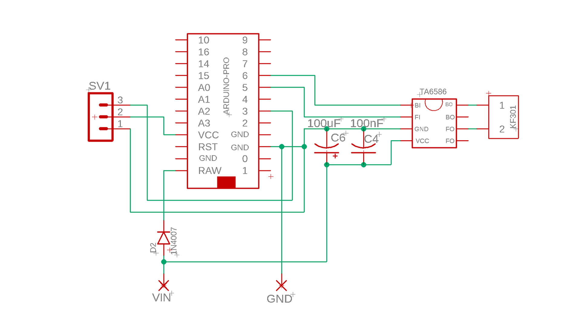
Limit switch diagram:
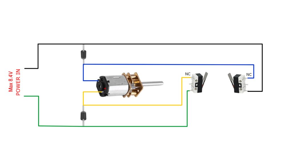
The motor should stop when the screw shaft reaches its endpoint. This is controlled by limit switches at both ends. If the motor does not stop when the shaft touches the limit switch, the motor polarity connections are incorrect. Reversing the solder connections of the motor polarity will solve the problem.
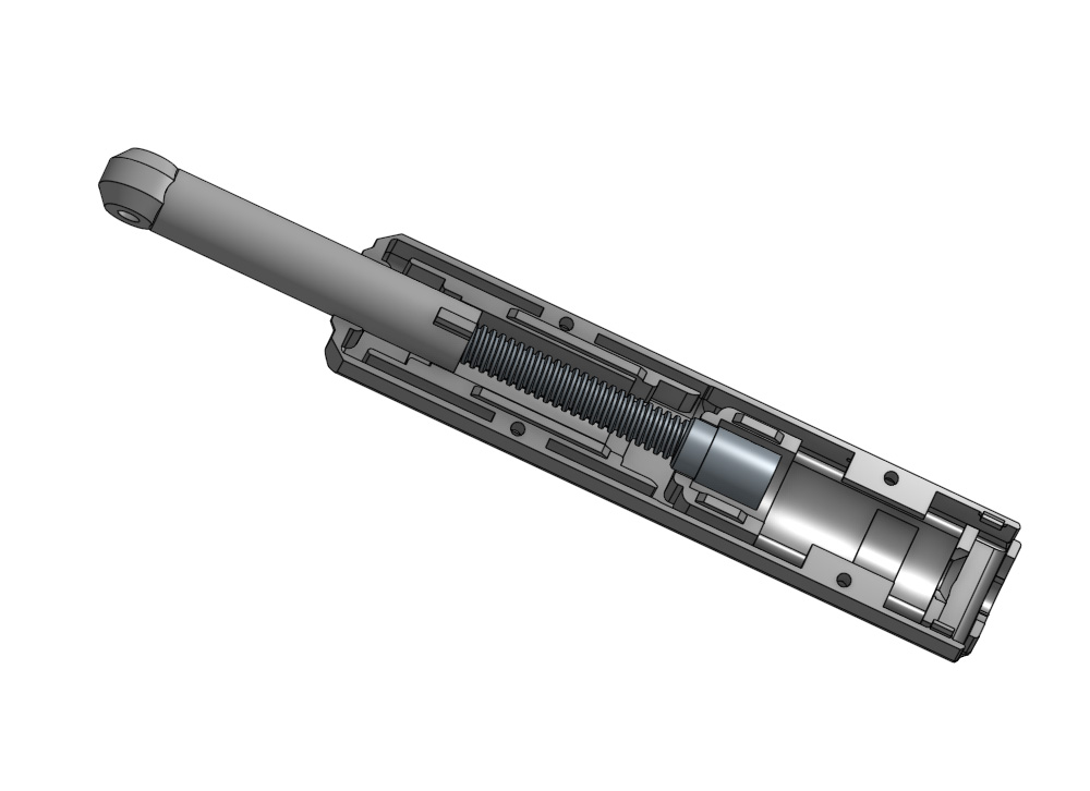
I chose PETG filament for 3D printing because PETG has a more fluid structure during mechanical movement. This allows the shaft to move much more smoothly.
After printing the shaft and shaft body, manually move the parts 3-4 times to ensure smooth movement. If the two parts don’t move smoothly, slightly reduce the filament flow rate in your slicing software settings. For example, you can try using 0.95 instead of 0.98. This will reduce friction between the parts during contact.
Print the shaft and shaft body at a low speed (maximum 60). I also recommend setting the layer thickness to 0.12 or 0.16.
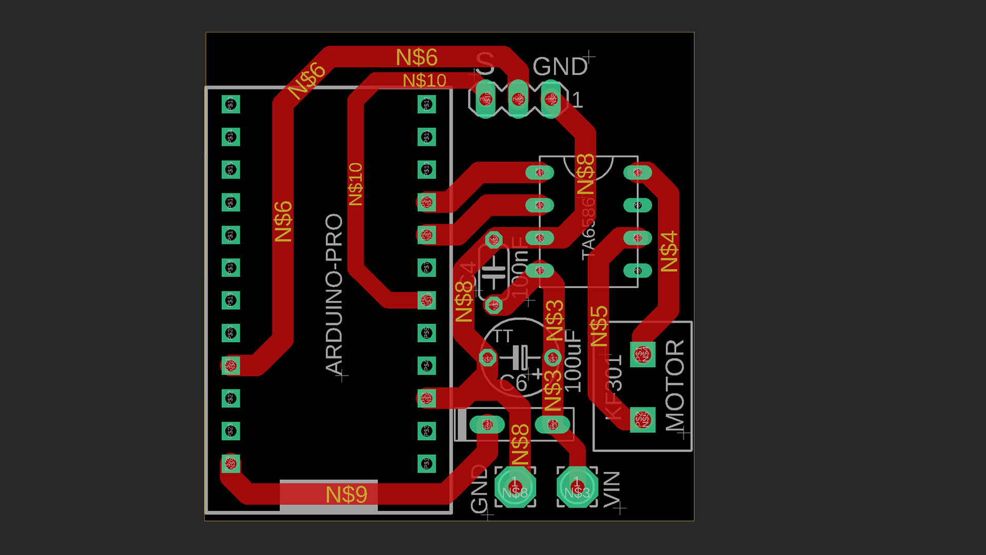
PDF of Lineer Actuator Circuit, Gerber Files, Arduino Code: https://drive.google.com/file/d/1T168OMJgCEb5yzt3M2t_KZCUSwRgONTD/view?usp=sharing
3D PRINTER FILES (Movement 27mm): https://cults3d.com/:4296738
3D FILES (Movement 40mm and 50mm): https://cults3d.com/:4369131
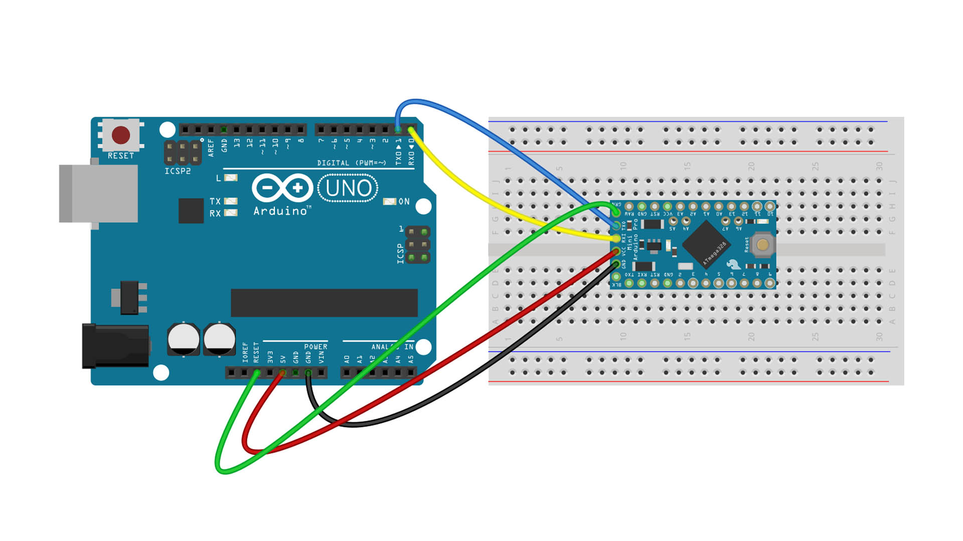
Lineer Activator Control Code For Arduino pro Micro:
					// ===== PINS =====
#define RC_PIN   3   // PWM input (INT0)
#define FI_PIN   5   // Forward
#define BI_PIN   6   // Backward

// ===== SETTING | AYARLAR =====
#define CENTER     1500
#define DEADZONE   20

#define MIN_PULSE  1000
#define MAX_PULSE  2000

#define SIGNAL_TIMEOUT 100000   // 100ms
#define HIGH_TIMEOUT   3000     // 3ms

#define MIN_SPEED  70   // motorun dönebileceği minimum PWM

// ===== VARIABLES |  DEĞİŞKENLER =====
volatile uint32_t riseTime = 0;
volatile uint32_t pulseWidth = 1500;
volatile uint32_t lastSignalTime = 0;
volatile bool signalHigh = false;


// ===== INTERRUPT =====
void pwmInterrupt() {
  if (digitalRead(RC_PIN) == HIGH) {
    riseTime = micros();
    signalHigh = true;
  } else {
    pulseWidth = micros() - riseTime;
    lastSignalTime = micros();
    signalHigh = false;
  }
}


void setup() {
  pinMode(RC_PIN, INPUT);

  pinMode(FI_PIN, OUTPUT);
  pinMode(BI_PIN, OUTPUT);

  motorStop();

  attachInterrupt(digitalPinToInterrupt(RC_PIN), pwmInterrupt, CHANGE);
}


void loop() {

  uint32_t now = micros();

  // ===== FAILSAFE =====
  if (signalHigh && (now - riseTime > HIGH_TIMEOUT)) {
    motorStop();
    return;
  }

  if (now - lastSignalTime > SIGNAL_TIMEOUT) {
    motorStop();
    return;
  }

  uint32_t pwm = pulseWidth;

  // ===== FILTER | FİLTRE =====
  static uint32_t lastValid = 1500;

  if (pwm >= MIN_PULSE && pwm <= MAX_PULSE) {
    lastValid = pwm;
  } else {
    pwm = lastValid;
  }

  int diff = pwm - CENTER;

  // ===== DEADZONE =====
  if (abs(diff) < DEADZONE) {
    motorStop();
    return;
  }

  // ===== SPEED CALCULATING | HIZ HESAPLAMA =====
  int speed = map(abs(diff), DEADZONE, 500, MIN_SPEED, 255);
  speed = constrain(speed, 0, 255);

  // ===== YÖN + PWM =====
  if (diff > 0) {
    motorForward(speed);
  } else {
    motorReverse(speed);
  }
}


// ===== MOTOR FUNCTIONS | MOTOR FONKSİYONLARI =====

void motorForward(int speed) {
  analogWrite(FI_PIN, speed);
  digitalWrite(BI_PIN, LOW);
}

void motorReverse(int speed) {
  analogWrite(BI_PIN, speed);
  digitalWrite(FI_PIN, LOW);
}

void motorStop() {
  digitalWrite(FI_PIN, LOW);
  digitalWrite(BI_PIN, LOW);
}
Materials needed for the control circuit:
N20 Gear Motor 6V (500 or 600 RPM): https://s.click.aliexpress.com/e/_c35s8Fap OR
https://s.click.aliexpress.com/e/_c4mC8ZBb
Arduino Pro Micro (5V): https://s.click.aliexpress.com/e/_c3J6yk7f OR https://s.click.aliexpress.com/e/_c3xktWgt
TA6586 DC Motor Driver DIP-8 IC: https://s.click.aliexpress.com/e/_c2x9EBvf OR https://s.click.aliexpress.com/e/_c3EEkt7F
Limit Switch : (KW10-2) https://s.click.aliexpress.com/e/_c3Tmvhu9 OR
(MS-0041A) https://s.click.aliexpress.com/e/_c4VwiKbB OR (Handle) https://s.click.aliexpress.com/e/_c3grRW0D
2.54 Header Pin: https://s.click.aliexpress.com/e/_c3aRosh3
PCB Screw Terminal Block (5mm-5.08mm): https://s.click.aliexpress.com/e/_c4V5gG5T OR https://s.click.aliexpress.com/e/_c4Tv1srP
100uF Capacitor: https://s.click.aliexpress.com/e/_c3WpDWyF
100nF Capacitor: https://s.click.aliexpress.com/e/_c4o6mz0n
Copper Board (Single side): https://s.click.aliexpress.com/e/_c3JlJSjv
2 pin JST & Cable: https://s.click.aliexpress.com/e/_c3OIELbT