How to make ampere, volt, watt meter circuit with Arduino Nano?
We use ACS714 20A current sensor for current measurement, a divider circuit consisting of 2 resistors and 0.96 inch Oled display for voltage measurement.
Voltage measurement: 7-24V
Max. current measurement : 20A
KendinYap Channel https://www.youtube.com/channel/UCgjJGE17yfovAvWUzEJFENA
Arduino Nano: https://www.banggood.com/custlink/3KGvbnJFwp
0.96 inc Oled Screen : https://www.banggood.com/custlink/D3mGpTMTGW
Necessary Materials:
Arduino Nano
0.96 inc Oled
ACS714 20A Current Sensor
5×5 cm PCB Board
UF4007 Diode
R1 Resistor 10K
R2 Resistor 1.5K
78M05 Regulator
0.1uF Capacitor
0.33uF Capacitor
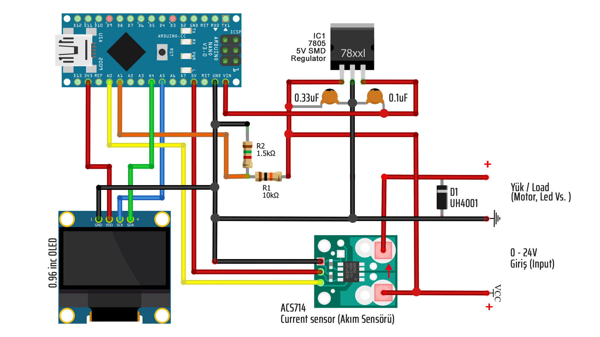
We use one diode in the load connection (Motor, Bulb etc. connection) section. The task of this diode is to prevent reverse voltage returning when the supply is interrupted in devices containing coils such as motors. The coils of the motors can accumulate electricity during operation and this accumulated electricity returns when the motor is stopped. This may disrupt the integrated components such as the circuit or cause interference.
The cathode side of the diode is soldered to the + pole direction. During the normal operation of the engine, normal operation takes place since the positive voltage cannot pass from the Cathode direction to the Anode side. When the motor is stopped, the returning current turns as reverse poles and the positive current enters the anode part, before it can return to the circuit, it turns on the diode and by returning to the motor and is damped in itself.
In order to use the circuit independently, we provide 5V supply to Arduino Nano with 7805 regulator integrated circuit. Since the 7805 regulator has a “lost voltage” value of approximately 2V, the voltage of the supply source should be minimum 7 volts.
The reason we use the divider circuit shown in the bottom diagram is that Arduino’s input pins support a maximum of 5 volts. Our circuit can be used up to 24V. In this case, thanks to the divider circuit, we can send the voltage to the analog input of Arduino after reducing the voltage below 5 volts. Otherwise, Arduino will be damaged.
The divider lowers the circuit input voltage proportionally. For this reason, the resistors forming the divider circuit are selected by taking into account the maximum input voltage of 24 volts. In this circuit, we use 10K as resistance R1 and 1.5K as resistance R2.
#include <Adafruit_GFX.h> //add libbrarry
#include <Adafruit_SSD1306.h>
Adafruit_SSD1306 display;

const int currentSensor = A0;
const int voltageSensor = A1;
float vOUT = 0.0;
float vIN = 0.0;
float R1 = 10000.0;
float R2 = 1980.0;
float Vdata = 0;
float V,I,I1;
float Cdata;
float value;

void setup(){

  display.begin(SSD1306_SWITCHCAPVCC, 0x3C);
  display.clearDisplay();
  display.setTextColor(WHITE);
  display.setTextSize(1);
  display.display();

}
void loop(){

//float vIN = 0.0;

   for(int i = 0; i < 300; i++) // Read 300 times to get a more stable average result
   {
     Cdata = Cdata + analogRead(currentSensor);
     Vdata = Vdata + analogRead(voltageSensor);
     delay(1);
   }

 Cdata=Cdata/300;
 V=(Cdata/1024.0)*5000;
 I=((V - 2500)/ 96);

 Vdata=Vdata/300;
 vOUT = (Vdata * 5.0) / 1024.0;
 vIN = (vOUT / (R2/(R1+R2)));

// OLED Ekrana Yazma
  display.setTextColor(WHITE);

  // Watt calculate and write on the screen
  display.setTextSize(1);
  display.setCursor(58,8);
  display.print(" Watt");
  display.setCursor(0,0);
  display.setTextSize(2);
  value=(I * vIN);
  if (value<0){display.println("0.0");} else {display.println(value);}

  // Amper value write on the screen
  display.setTextSize(1);
  display.setCursor(58,23);
  display.print(" Amper");
  display.setCursor(0,16);
  display.setTextSize(2);
  if (I<0) {display.println("0.0");} else {display.println(I);}

  // Voltage value write on the screen
  display.setTextSize(1);
  display.setCursor(58,39);
  display.print(" Volt");
  display.setCursor(0,32);
  display.setTextSize(2);
  display.println(vIN);

display.display();
display.clearDisplay();

// Resetting values
  Cdata=0;
  I=0;
  V=0;
  Vdata=0;
  vIN=0;
  value;
}
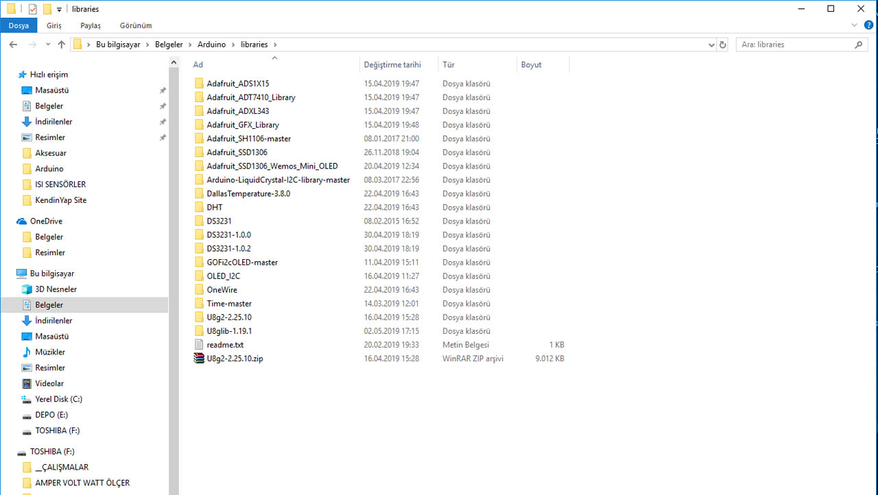
SSD1306 librarry link used in code for OLED Display. You should copy the library file you downloaded from this link to the Documents / Arduino / Libraries folder as in the picture below. The library related to the #include command at the top of the code is included in the code.
Voltage Calibration:
The values of the resistors we use in the circuit are assigned to the variables R1 and R2 in the code. So this code should also take values of R1 (10K) 10000 and R2 (1.5K) 1500. In practice, these values do not reflect accurate voltage measurement. Therefore, we get the correct voltage value by making changes in these values for calibration purposes. We measure the voltage we supply the circuit with a multimeter and we can find the correct result by changing the value of the R2 variable in plus or minus direction until we get a value that is equal to or very close to this voltage value.
When I made the R2 value in the code section for my circuit in 1980 (1.98K), I got a near-perfect result. In the video, I tested with two different voltages namely 2S and 3S Lipo batteries, but I also tested very different voltage values with a regulator other than video. And each time I received equal values from the multimeter, with the exception of a negligible difference of about + – 0.02 volts.
Current (Amper) Calibration:
We use ACS714 current sensor in this circuit. This sensor is available in 5A / 20A / 30A versions. We use 20A, that is, a version capable of measuring up to 20 amps, and its output sensitivity is 100 mV / A. We use this value as a divider in the formula I (current) in line 38. These values are theoretical values. The product coming out of production may not give these values exactly. So I used this code as 96 instead of 100 for calibration.
Note: 185mV / A for the 5-amp version and 66mV / A for the 30-amp version
Finally, for more stable results, Voltage and Current values are read 300 times and averaged of these values are displayed on the screen. In addition, the power value in watts is obtained by multiplying Volt and Ampere values (P = I * V).
Note: It is my choice to read 300 times in the loop. There may also be less or more. As a result of my tests, I decided that a value of 250-300 is enough to get a stable result.
IMPORTANT: External calibration should not be performed while connected to the computer from Arduino USB for calibration trials. Because the 5V Arduino that goes through the regulator feeds the Vin input and the voltage coming from two directions may cause the Arduino or your computer to malfunction.
Making such circuits requires basic practical skill and attention. The problems that may arise are under the control of the person. You are responsible for any undesired consequences such as malfunction or injury.