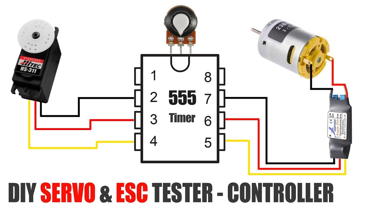
PWM driver circuit to test Rc servos and Rc ESCs and operate them without the need for Radio Control.
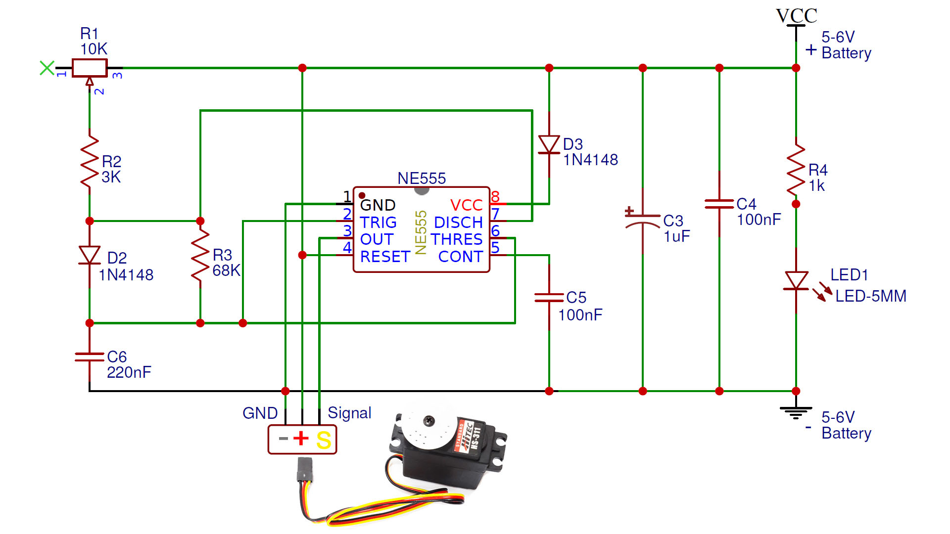
Usually the circuit is powered by 5-6V because Servo motors operate with 5-6V. If the servo to be operated requires higher voltage, the supply voltage can also be increased (Max 12V). This circuit can drive an ESC or a Servo motor. RC Esc and servo motors can be controlled by PWM signal. It generates PWM signal with NE555 or LE555 Timer IC that we use in the circuit. (DC motors cannot be operated directly with this circuit)
You Needs:
Resistors: https://www.banggood.com/custlink/GKvv6WbZy0
1N4148 Diodes: https://www.banggood.com/custlink/GvvK2E9cy9
555 Timer IC: https://www.banggood.com/custlink/vmGv2hScrt
100nF (0.1uF) capacitor: https://www.banggood.com/custlink/v3DGOAqc2e
Capacitors: https://www.banggood.com/custlink/G3vmqd8cWh
10K Potentiometer: https://www.banggood.com/custlink/vmvGaQUWTG
5mm LED: https://www.banggood.com/custlink/KmGDofvZMQ
PCB Board: https://www.banggood.com/custlink/KmKvqh8Crb
1K ohms Resistor
3K ohms Resistor
68K ohms Resistor
2 x 1N4148 Diyode
220nF Ceramic Capacitor
100nF Ceramic Capacitor
1uF 50V Capacitor
NE555 Timer
5mm Led
10K Potantiometer
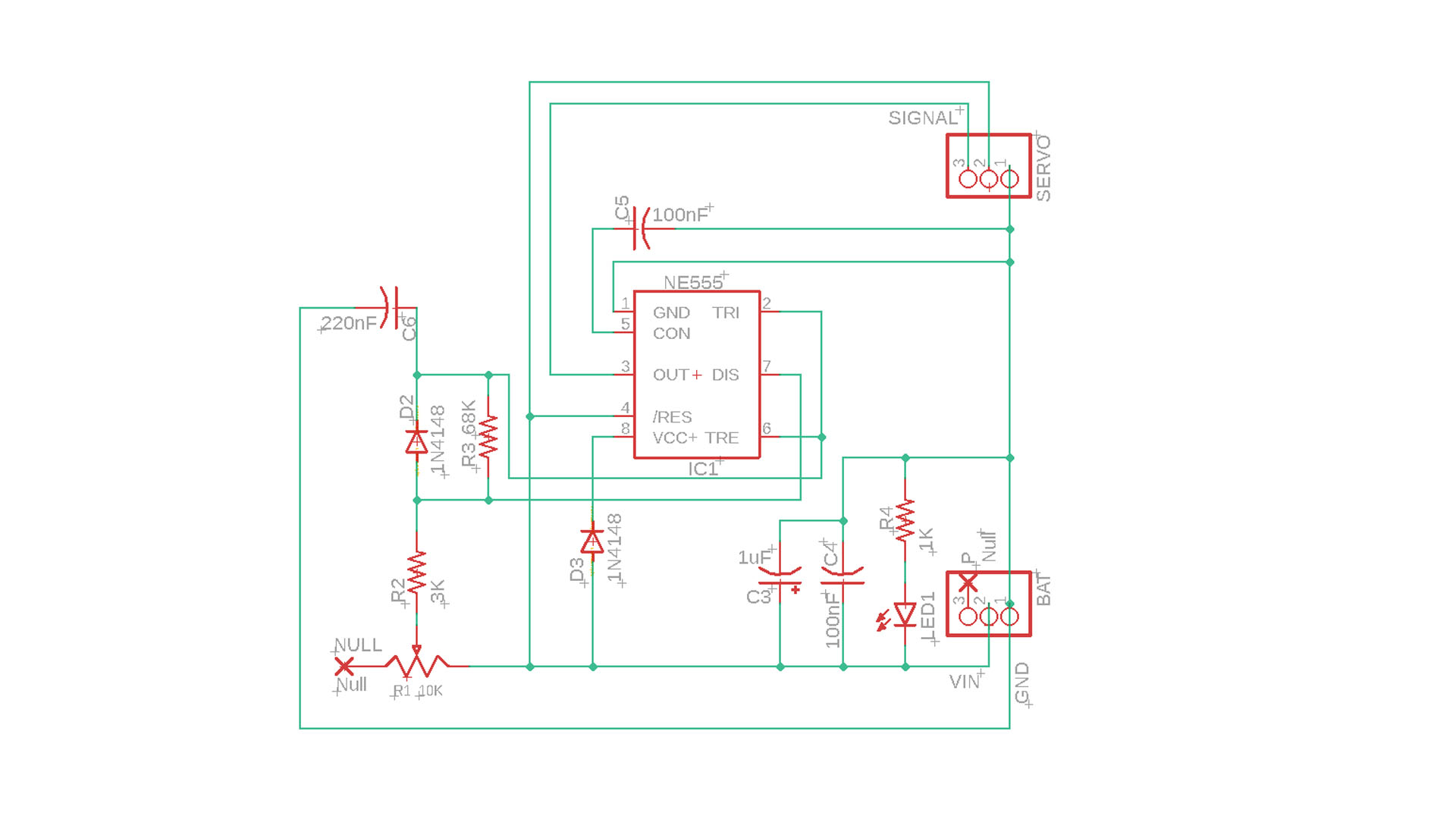
Servo & ESC Driver Circuit
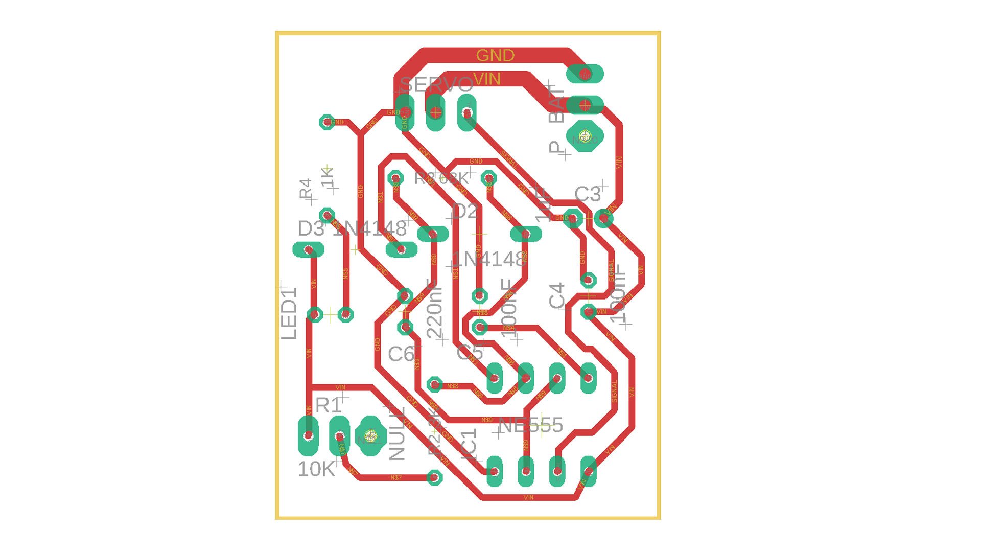
PDF and Gerber Files: https://drive.google.com/file/d/1TBOW2ZMDhbdxdZ5HzfU9bIHEu9CQwMQV/view?usp=sharing