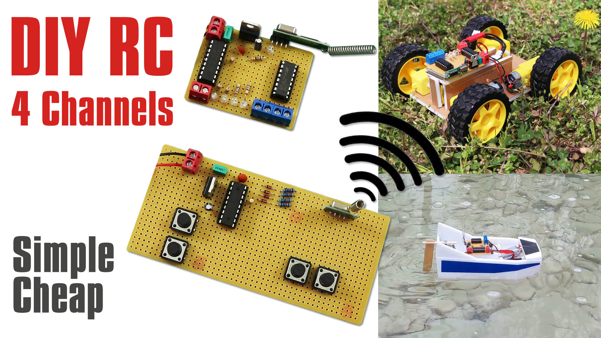
RF 4 Channel Remote Control construction with PT2262 Encoder and PT2272 M4 Decoder integration.
I used 433Mhz RF modules in this circuit. With the RX470-4 receiver and WL102-341 transmittermodule, it is possible to reach a range of 100 meters in ideal conditions. This range is more than enough for small RC model vehicles. Longer range can be achieved by using different RF modules in the same circuit. In theory up to 4km is possible.
The remote control system consists of a transmitter with 4 buttons and a receiver with L293B integrated, which can drive 2 motors independently. L293D can also be used as a motor driver. L293D has a maximum current support of 0.6 Amps for each motor. L293B, on the other hand, can provide 1 Ampere support continuously. If the current drawn by the motors you will use is not greater than 0.6A, you can use the relatively cheaper L293D.
L7805 5V Regulator: https://s.click.aliexpress.com/e/_DDvYt5v
0.33uF (330nF) Capacitor & 0.1uF (100nF) Capacitor: https://s.click.aliexpress.com/e/_DDGpTwv
10uF 25V Capacitor: https://s.click.aliexpress.com/e/_DEgSnr7
PT2262 Encoder IC: https://s.click.aliexpress.com/e/_DlPZhL3
PT2272 M4 Decoder IC: https://s.click.aliexpress.com/e/_DlPZhL3
18 Pin IC socket: https://s.click.aliexpress.com/e/_Dlx5uRP
RF Transmitter & Receiver module: https://s.click.aliexpress.com/e/_DBVxEEz
1N4148 Diodes: https://s.click.aliexpress.com/e/_DdIhb5D
1.2M, 200K and 680R resistors: https://s.click.aliexpress.com/e/_DCoK93F
12mm Tach Button: https://s.click.aliexpress.com/e/_DmVZvZZ
3mm Leds: https://s.click.aliexpress.com/e/_DD8EcNb
L293B Motor Driver IC: https://s.click.aliexpress.com/e/_DmJtzRF
Gear motor: https://s.click.aliexpress.com/e/_DnCTIYt
9V battery Connector: https://s.click.aliexpress.com/e/_De32c1L
9V Battery
The commands are not proportional in this type of circuit. It provides commands such as Open-Close / Forward-Back / Right-Left. It can be used in many non-sophisticated RC vehicle applications and with devices that want to be controlled wirelessly.
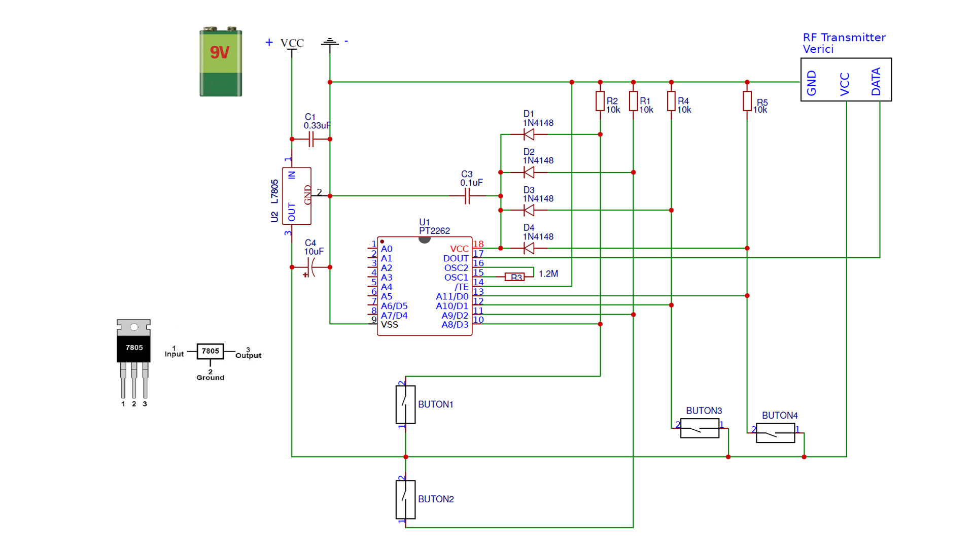
RF Transmitter Circuit Diagram:
Required Materials and their duties in the Circuit:
L7805 5V Regulator (Reduces the input voltage to a constant 5v for the regulator section)
0.33uF Capacitor (filters possible electrical interference at input voltage for 5v regulated section)
0.1uF Capacitor (5v regulated section filters out possible small electrical interference)
10uF 25V Capacitor (filters possible relatively large electrical interference in output voltage for 5v regulated section)
PT2262 Encoder IC (encodes the signal sent to the RF transmitter module)
18 Pin IC socket Optional. It is used when the integrated leg is not desired to be soldered.
RF Transmitter module (Used to wirelessly transmit the data generated by the Integration) 4 x 10K Resistors (Resistors for pulldown purposes; It prevents instability caused by interference that may occur due to the momentary idle circuit ends while pressing or releasing the buttons)
TX & RX Modul ( WL102-341 & RX470-4)
4 x 1N4148 Diodes (When the button is not pressed, it prevents electricity from going to the integrated, ensuring stable operation of the transmitter)
1.2M Resistor (Connected between the Integrated OSC outputs and determines the frequency. There should not be a random resistor. Which values can be used resistors are specified in the PT2262 Datasheet)
4 x (12X12)mm Tach Button (Buttons can be of different size or type. Momentary push type is sufficient)
9V Battery (The regulation circuit supports up to 18V, but it is recommended to use a supply between 7-9 volts for efficiency. Ideally it can be a 9V battery or 7.4V LiPo. The supply
voltage should not be less than 7 volts. Because about 2V of the energy passing through the 7805 is the drop voltage. (In a sense, it can be called lost voltage.) That is, if we feed it with 6V, the output will be 4V. The ideal operating voltage of the transmitter is 5V. Low voltage range also negatively affects. Therefore, we can say that between 7V and 9V is the ideal supply voltage.
The buttons can be shaped according to the vehicle we want to control. The positions in the diagram are ideal for classic Rc car and boat. But for Rc tanks or similarly moving vehicles, if the buttons on the right are placed like the ones on the left, a more practical use is obtained.
The receiver circuit works with a 9V battery, but a second power supply is required for the motors. That’s why we connect a second battery to the motor supply input. Technically, both the receiver circuit and the motors can be powered from a single battery. But this situation causes electrical interference and can prevent the stable operation of the circuit. In practice, two separate power supplies are required for stable operation.
I used 7.4V LiPo for the motors, but different batteries can also be used. For example, 4 or 6 AA batteries (connected in series) or 2 18650 Li-ion batteries (connected in series), etc.
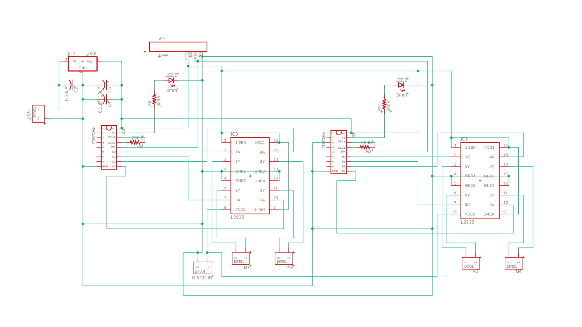
RF Receiver Circuit Diagram:
Required Materials and their duties in the Circuit:
L7805 5V Regulator (Reduces the input voltage to a constant 5v for the regulator section)
0.33uF Capacitor (filters possible electrical interference at input voltage for 5v regulated section)
0.1uF Capacitor (5v regulated section filters out possible small electrical interference)
10uF 25V Capacitor (filters possible relatively large electrical interference in output voltage for 5v regulated section)
PT2272 M4 Decoder IC (decodes the signal coming to the RF receiver module and activates the corresponding channel output):
2×18 Pin IC socket Optional. It is used when the integrated leg is not desired to be soldered.
5 x 680R Resistor (It is used to reduce the current to the LEDs indicating the signal coming and which channel the command is coming in. Because the voltage output from PT2272 is high for LEDs)
5 x 3mm Leds (Indicates which channel is active.
200K Resistor (Connected between the Integrated OSC outputs and determines the frequency. There should not be a random resistor. Which values can be used resistors are specified in the PT2272 Datasheet)
RF Receiver Module (Receives the data received with the signal and sends it to the decoder integrated)
L293B Motor Driver IC (Directs DC motors according to commands from decoder)
16 Pin IC socket Optional. It is used when the integrated leg is not desired to be soldered
Gear motors
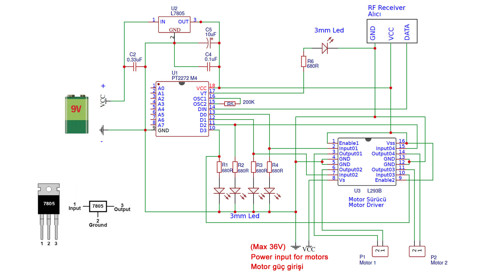
The circuit has two motor connections. In the sample vehicle in the video, 4 engines are used. The cables of the 2 motors on the right are connected in parallel to each other and act like a single motor. Likewise for the two engines on the left.
This circuit can be used with different applications other than RC vehicles. It is also suitable for functions such as turning on light, remotely turning on / off any electrical device by using the appropriate relay instead of the motor driver.
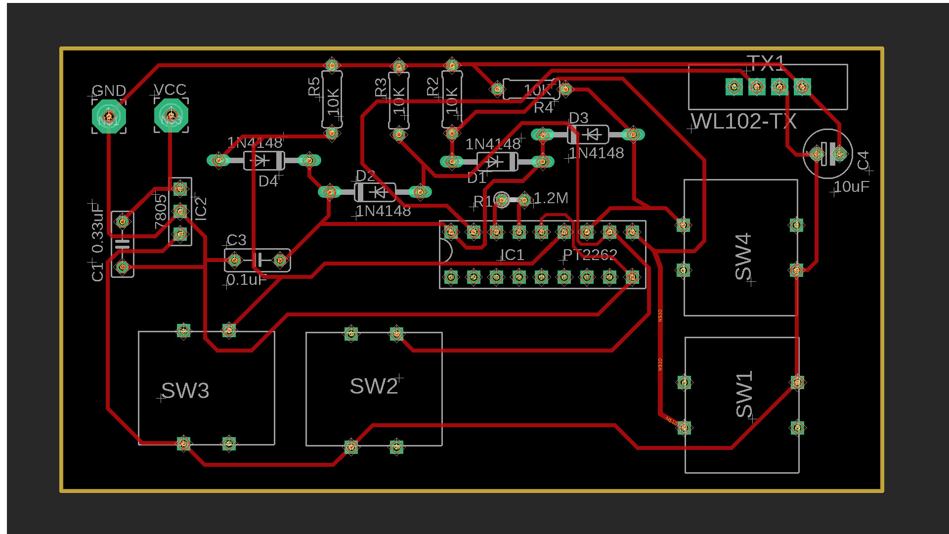
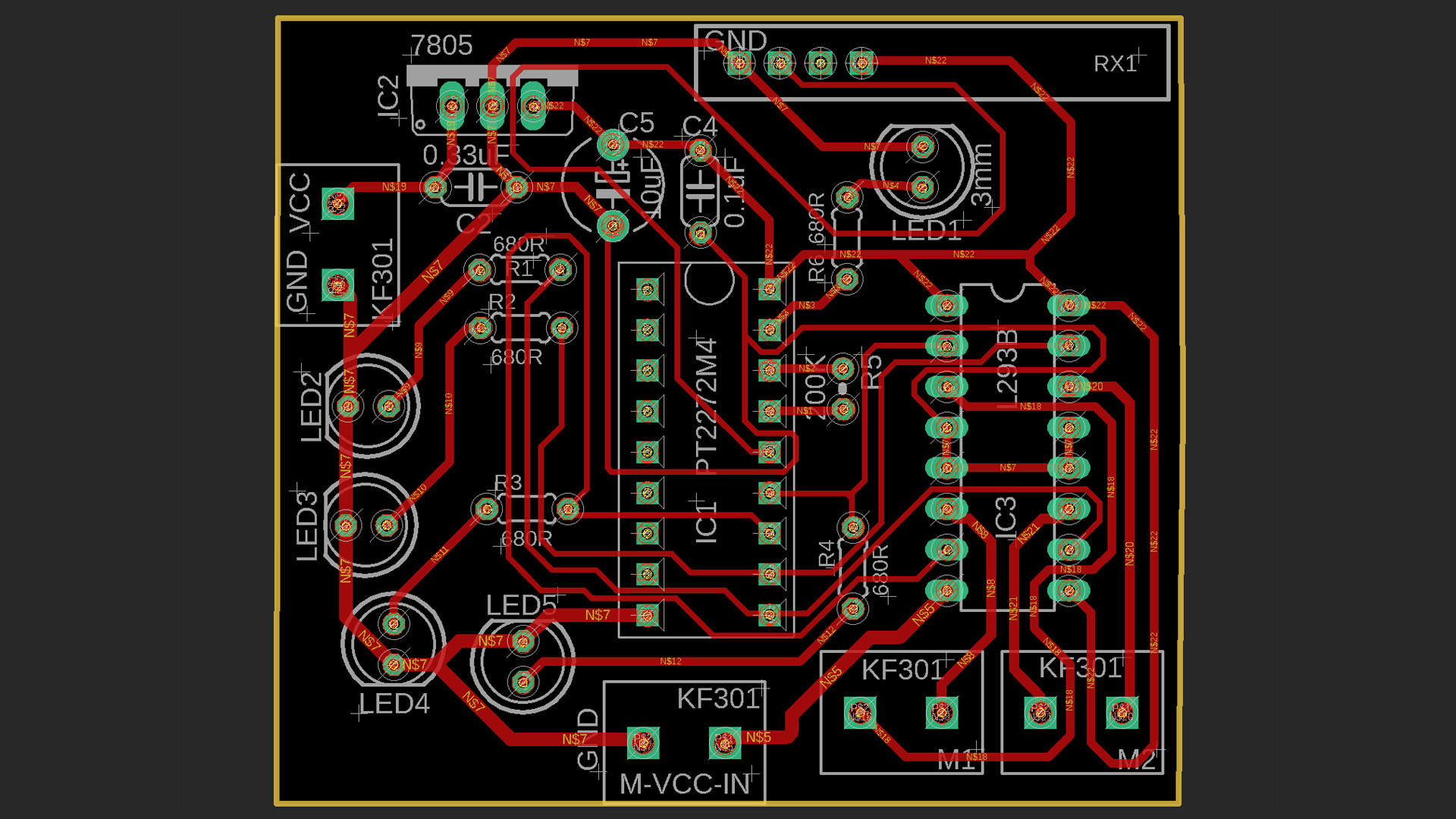
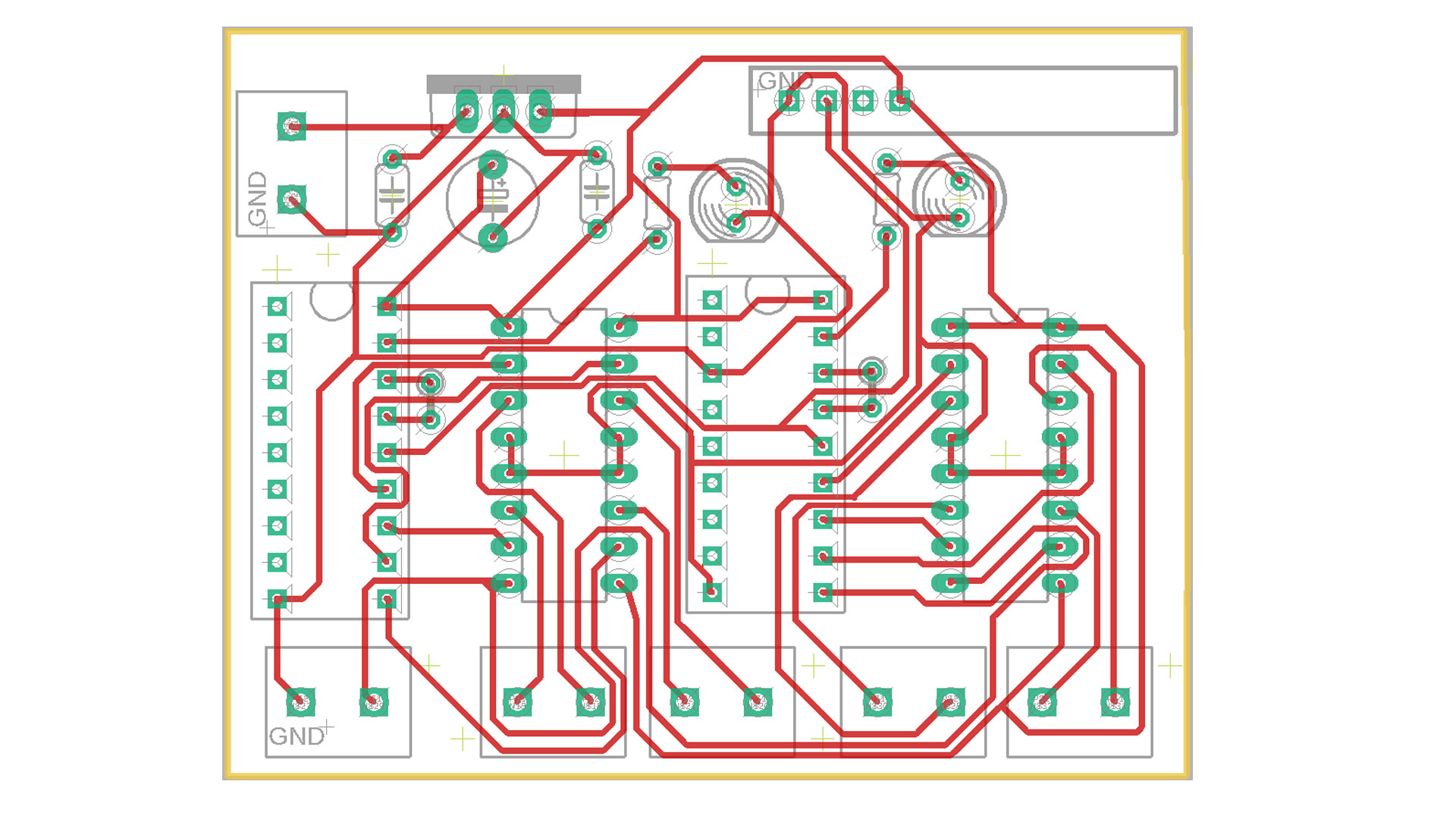
4-Channel RF PDF and GERBER Files: https://drive.google.com/file/d/1c42D1N3ItGWrNEprOk5rBQhHtyaG3bPv/view?usp=sharing
OPTIONAL:
8-Channel RF Transmitter and Receiver (Remote Control) PDF and Gerber Files: https://drive.google.com/file/d/1EFZdg-oFIHEitMzBMoW45SQyWYvnyuIQ/view?usp=sharing
8 Channel RECEIVER CIRCUIT: 7V -25V batteries can be used to supply the RF receiver circuit (VCC). Recommended 7.4V (2S) Lipo, 2S Li-on, 5 x AA batteries (with battery box), 6 x AA batteries (with battery box) veya 9V battery.
The “M-VCC-IN” input is for powering the motors. 4 motors can be connected. Each motor must draw a maximum of 1A of power. Motor power input can be maximum 32V. Recommended maximum 12V
8 Channel TRANSMITTER CIRCUIT: 7V -25V batteries can be used to supply the RF transmitter circuit (VCC). Recommended 7.4V (2S) Lipo, 2S Li-on, 5 x AA batteries (with battery box), 6 x AA batteries (with battery box) veya 9V battery.