09/16/2026

Converting Your Gamepad into an 8-Channel Remote Control

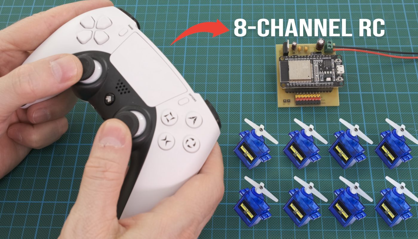
You can convert your game controller into an 8-channel remote by building a simple receiver circuit. All you need is an ESP32 microcontroller and a few other electronic components.

What is needed?

ESP32 Dev Kit V1 (30 Pin): https://s.click.aliexpress.com/e/_c4s768qf
7806 Voltage Regulator IC: https://s.click.aliexpress.com/e/_c3pJ16Jp
2.54 Header Pin: https://s.click.aliexpress.com/e/_c3aRosh3
Terminal Block Connector KF350 (3.5mm): https://s.click.aliexpress.com/e/_c3M3xTMn
100uF Capacitor: https://s.click.aliexpress.com/e/_c3WpDWyF
100nF Capacitor: https://s.click.aliexpress.com/e/_c4o6mz0n
Copper Board (Single side): https://s.click.aliexpress.com/e/_c3JlJSjv
2 pin JST & Cable: https://s.click.aliexpress.com/e/_c3OIELbT
3A Diode: https://s.click.aliexpress.com/e/_c2xsmj2b
1A Diode: https://s.click.aliexpress.com/e/_c3XP2xyX

Gamepad  PS3-PS4 or an equivalent (It must have Bluetooth and HID Protocol support) 
My Gamepad: Deadskull P09 (Third-party production)


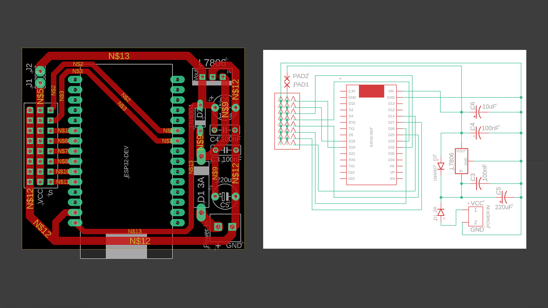
You can build this circuit using 3 different methods. A handmade PCB like the one I made (link for PDF file below). 

Or, you can build the circuit on a perforated board.
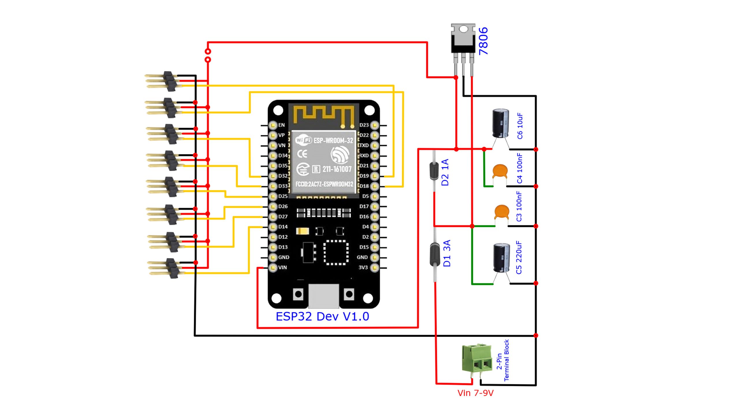
Simplified diagram:


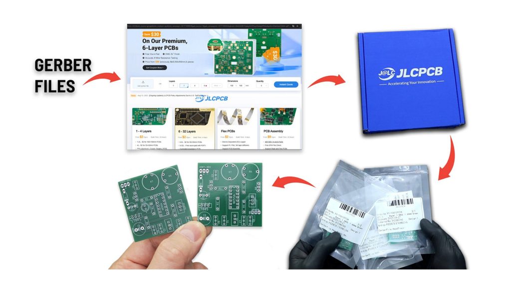
Or you can opt for the professional method, JLCPCB. Link to Gerber files is below.


JLCPCB for your professional PCB needs. Quality, Reliable, Fast …

New users get $123 coupons: https://jlcpcb.com/?from=RCMakerLab2 Multi-Layer PCBs without compromise – JLCPCB offers 6‑ to 32‑layer boards with free via-in-pad (saves routing space, lowers layer count) and ±10% impedance control for signal integrity, Start your project now.


Circuit diagram, PDF, Gerber Files, ESP32 Codes: 

https://drive.google.com/file/d/17ONaZsQ2ykHABbTequudpERJRF3TWHTf/view?usp=sharing

Before uploading the remote control receiver code to the ESP32, you may need to install the test program. The button and joystick values may not be the same for every gamepad.

To view the button and joystick values, install and run the test program. Pair your gamepad with the ESP32. Open the Serial monitor window.

Move the joystics and press the buttons. If the values displayed on the screen do not match the code, update the values in the relevant section.

These were the values for my gamepad:

// Button map (P09 example – change if required)
#define BTN_L1 64
#define BTN_L2 16
#define BTN_R1 128
#define BTN_R2 32

#define BTN_KARE1 1
#define BTN_KARE2 2
#define BTN_KARE3 4
#define BTN_KARE4 8

The values ​​-512 and +512 are the maximum joystick values:

int calcAxis(int value,uint8_t ch)
{
value=constrain(value,-512,512);
if(reverseCh[ch]) value=-value;
if(abs(value)<DEAD_BAND) value=0;
int us=map(value,-512,512,minUs[ch],maxUs[ch]);

NOTE: Run the test program with the ESP32 connected to your computer via USB, independently of the circuit.


Receiver Code For ESP32 Dev Kit V1 (30 Pin):

				
					/*
ESP32 Bluetooth HID RC Receiver
Version 1.2.0
Framework for Bluepad32 compatible Bluetooth HID controllers.

NOTE:
- Update BTN_* values after identifying your controller.
- Channels 5-8 are servo channels driven by buttons.
*/
21
#include <Bluepad32.h>
#include <ESP32Servo.h>

//================ USER SETTINGS ====================

#define CHANNEL_COUNT 8

// Servo Pins
const uint8_t servoPins[CHANNEL_COUNT] = {
  19, // CH1 Roll
  18, // CH2 Throttle
  32, // CH3 Yaw1
  33, // CH4 Pitch
  25, // CH5 L1/L2
  26, // CH6 R1/R2
  27, // CH7 Kare1/Kare2
  14  // CH8 Kare3/Kare4
};

// Button map (P09 example - change if required)
#define BTN_L1      64
#define BTN_L2      16
#define BTN_R1      128
#define BTN_R2      32

#define BTN_KARE1   1
#define BTN_KARE2   2
#define BTN_KARE3   4// Button map (P09 example - change if required)
#define BTN_L1      64
#define BTN_L2      16
#define BTN_R1      128
#define BTN_R2      32

#define BTN_KARE1   1
#define BTN_KARE2   2
#define BTN_KARE3   4
#define BTN_KARE4   8

#define DEAD_BAND 15

bool reverseCh[CHANNEL_COUNT]={
  false,false,false,false,false,false,false,false
};

int centerUs[4]={
  1500,1500,1500,1500
};

int minUs[CHANNEL_COUNT]={
 1000,1000,1000,1000,1000,1000,1000,1000
};

int maxUs[CHANNEL_COUNT]={
 2000,2000,2000,2000,2000,2000,2000,2000
};

int failsafeUs[CHANNEL_COUNT]={
 1500,1500,1500,1500,1500,1500,1500,1500
};

//===================================================

ControllerPtr controller=nullptr;
Servo servo[CHANNEL_COUNT];

uint32_t lastPrint=0;

void onConnectedController(ControllerPtr ctl){
  controller=ctl;
  Serial.println("Controller Connected");
}

void onDisconnectedController(ControllerPtr ctl){
  controller=nullptr;
  Serial.println("Controller Disconnected");
}

int calcAxis(int value,uint8_t ch)
{
  value=constrain(value,-512,512);

  if(reverseCh[ch]) value=-value;

  if(abs(value)<DEAD_BAND) value=0;

  int us=map(value,-512,512,minUs[ch],maxUs[ch]);

  int delta=centerUs[ch]-1500;
  us+=delta;

  return constrain(us,minUs[ch],maxUs[ch]);
}

void applyFailsafe()
{
  for(int i=0;i<CHANNEL_COUNT;i++)
    servo[i].writeMicroseconds(failsafeUs[i]);
}

void setup()
{
  Serial.begin(115200);

  for(int i=0;i<CHANNEL_COUNT;i++){
    servo[i].setPeriodHertz(50);
    servo[i].attach(servoPins[i],1000,2000);
  }

  applyFailsafe();

  BP32.setup(&onConnectedController,&onDisconnectedController);

  Serial.println();
  Serial.println("ESP32 Bluetooth HID RC Receiver");
  Serial.println("Version 1.1.0");
  Serial.println("Waiting controller...");
}

void processButtons(uint16_t b)
{
  // CH5
  if(b & BTN_L1) servo[4].writeMicroseconds(maxUs[4]);
  else if(b & BTN_L2) servo[4].writeMicroseconds(minUs[4]);
  else servo[4].writeMicroseconds(centerUs[0]);

  // CH6
  if(b & BTN_R1) servo[5].writeMicroseconds(maxUs[5]);
  else if(b & BTN_R2) servo[5].writeMicroseconds(minUs[5]);
  else servo[5].writeMicroseconds(1500);

  // CH7
  if(BTN_KARE1 && (b & BTN_KARE1)) servo[6].writeMicroseconds(maxUs[6]);
  else if(BTN_KARE2 && (b & BTN_KARE2)) servo[6].writeMicroseconds(minUs[6]);
  else servo[6].writeMicroseconds(1500);

  // CH8
  if(BTN_KARE3 && (b & BTN_KARE3)) servo[7].writeMicroseconds(maxUs[7]);
  else if(BTN_KARE4 && (b & BTN_KARE4)) servo[7].writeMicroseconds(minUs[7]);
  else servo[7].writeMicroseconds(1500);
}

void loop()
{
  BP32.update();

  if(!controller || !controller->isConnected()){
    applyFailsafe();
    return;
  }

  int ch[4];
  ch[0]=calcAxis(controller->axisX(),0);
  ch[1]=calcAxis(controller->axisY(),1);
  ch[2]=calcAxis(controller->axisRX(),2);
  ch[3]=calcAxis(controller->axisRY(),3);

  for(int i=0;i<4;i++)
    servo[i].writeMicroseconds(ch[i]);

  processButtons(controller->buttons());

  if(millis()-lastPrint>200){
    lastPrint=millis();
    Serial.printf("CH1=%d CH2=%d CH3=%d CH4=%d BTN=%u\n",
      ch[0],ch[1],ch[2],ch[3],controller->buttons());
  }
}


ESP32 DevKit 30-Pin + Bluepad32 Arduino IDE Setup Guide

This guide explains how to set up a classic 30-pin ESP32 DevKit / ESP32-WROOM-32 board in Arduino IDE and install Bluepad32 for Bluetooth gamepad projects.

1. Install Arduino IDE

Install and open Arduino IDE 2.x.

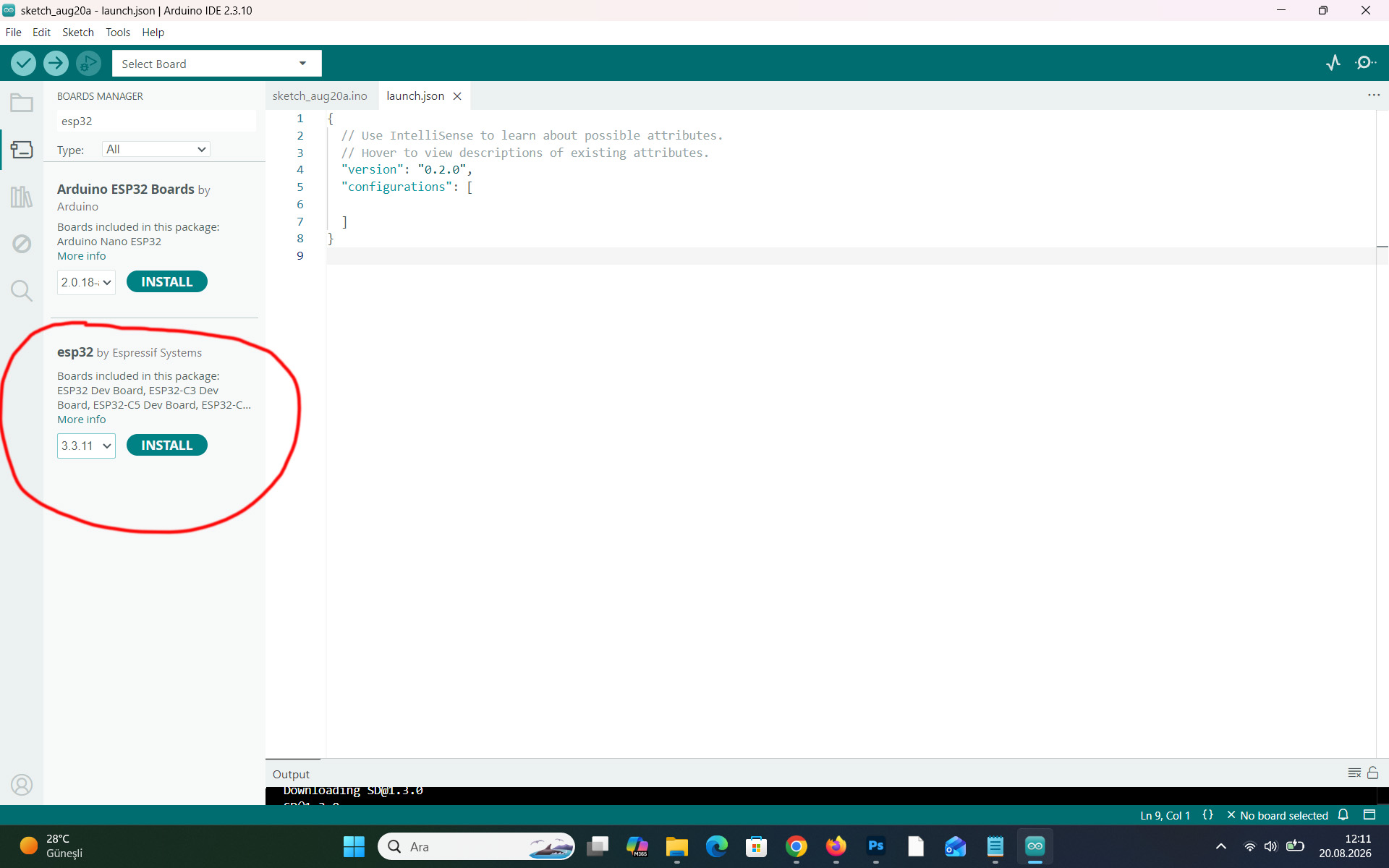
2. Install the ESP32 Board Package

Go to:

File → Preferences → Additional Boards Manager URLs

Add the official Espressif ESP32 package URL:

https://espressif.github.io/arduino-esp32/package_esp32_index.json
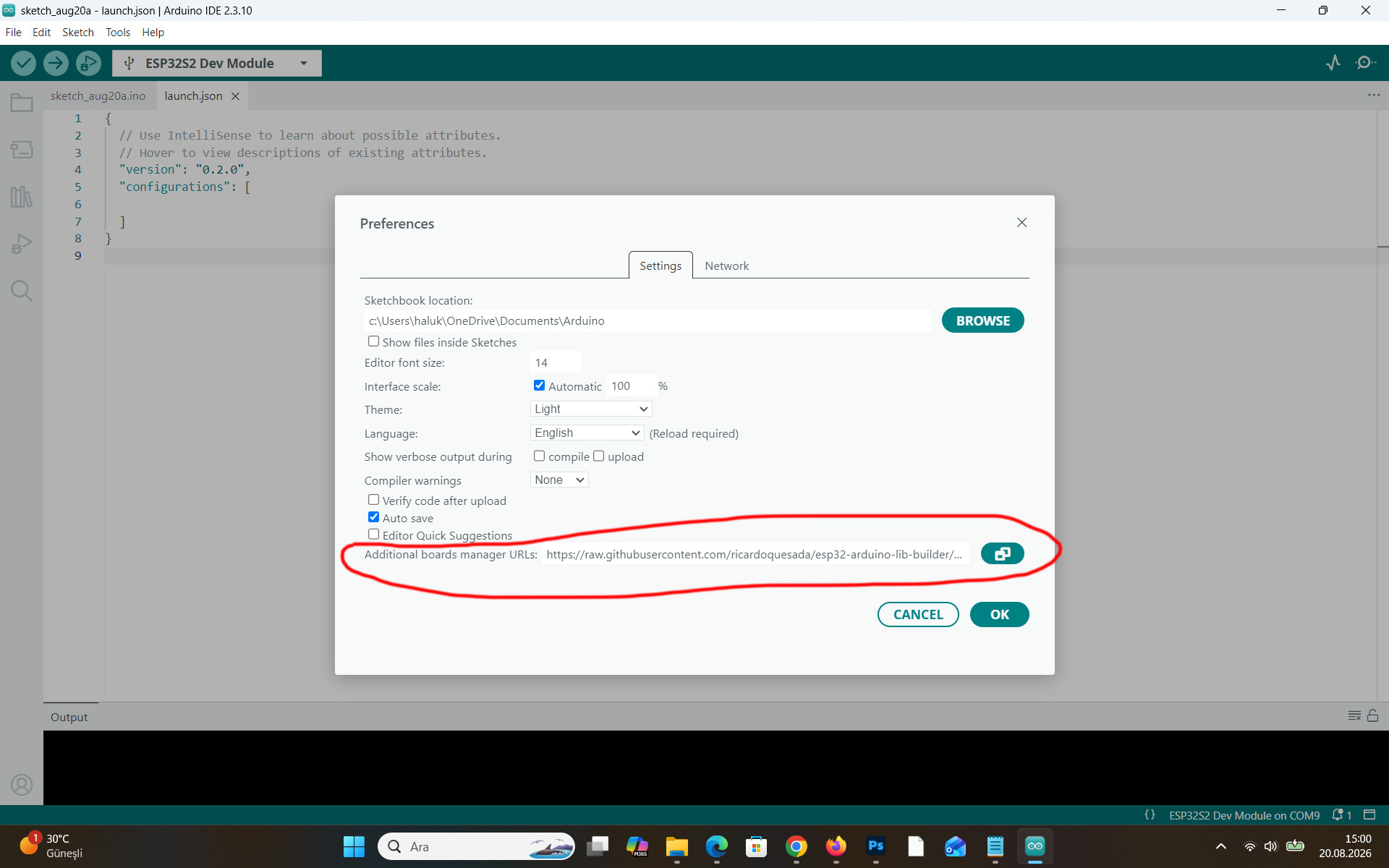
Then open:

Tools → Board → Boards Manager

Search for:

esp32

Install:

esp32 by Espressif Systems

3. Install Bluepad32 Board Support

(For the gamepad to establish a Bluetooth connection with the ESP32)

Go back to:

File → Preferences → Additional Boards Manager URLs

Add the Bluepad32 package URL:

https://raw.githubusercontent.com/ricardoquesada/esp32-arduino-lib-builder/master/bluepad32_files/package_esp32_bluepad32_index.json

If another URL is already present, keep it and add this URL as a separate entry.
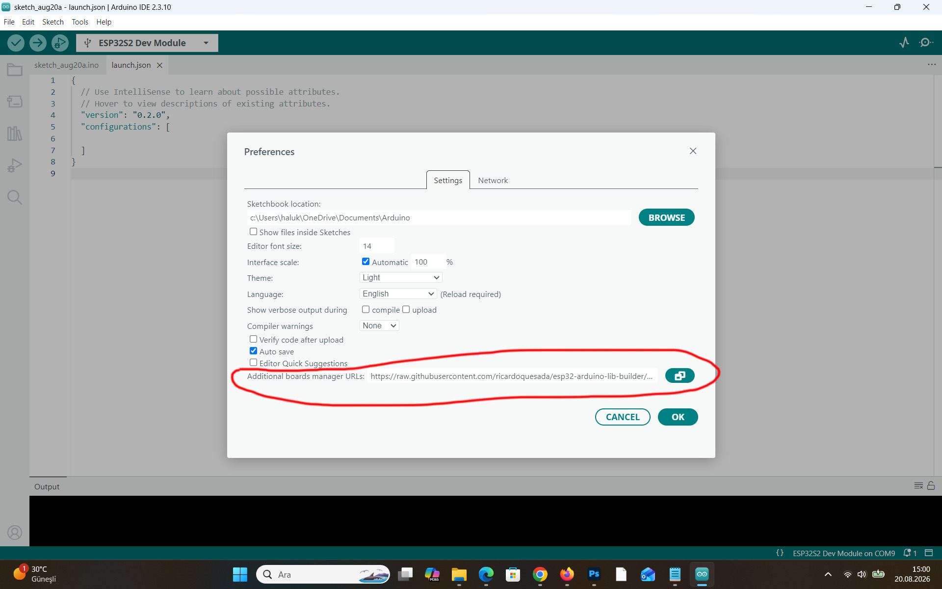
Then open:

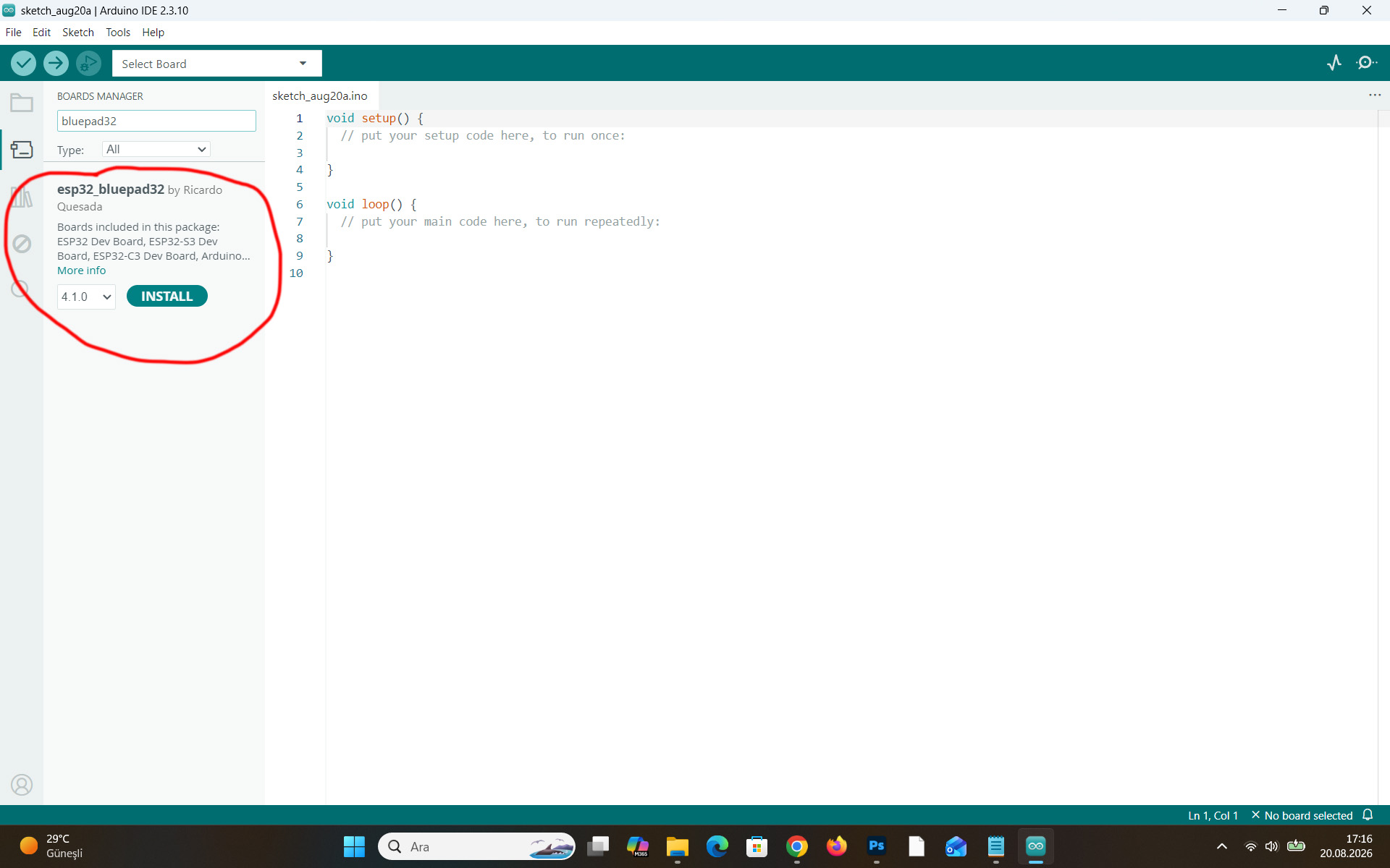
Tools → Board → Boards Manager

Search for:

Bluepad32

Install:

ESP32 + Bluepad32

This is the board package that provides Bluepad32 support for Arduino-based ESP32 projects.
4. Select the ESP32 DevKit Board

Connect the 30-pin ESP32 DevKit to the computer through USB.

In Arduino IDE, select:

Tools → Board → ESP32 + Bluepad32 → ESP32 Dev Module
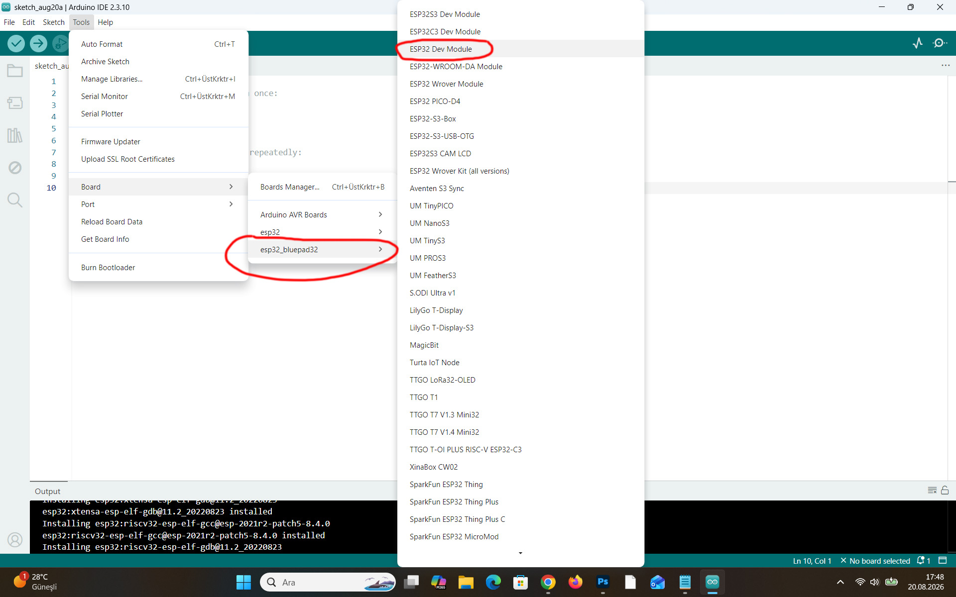
For a typical ESP32-WROOM-32 / 30-pin DevKit board, ESP32 Dev Module is an appropriate general-purpose selection.

Then select the correct USB port under:

Tools → Port

For example:

COM5

The actual COM number depends on the computer.

5. Install the Required Libraries

Open:

Tools → Manage Libraries

Search for and install:

Bluepad32

For projects that control servos, also install:

ESP32Servo

6. Test the ESP32

Before testing Bluetooth, it is useful to verify that the ESP32 can be programmed correctly.

A simple test program is:

void setup() {
  Serial.begin(115200);
  Serial.println("ESP32 OK!");
}

void loop() {
}

Upload the program and open:

Tools → Serial Monitor

Set the baud rate to:

115200

The following message should appear:

ESP32 OK!

If uploading stops at something similar to:

Connecting........

press and hold the BOOT button on the ESP32 while the upload process starts, then release it once programming begins.

7. Test Bluepad32

Open one of the Bluepad32 example programs from:

File → Examples → Bluepad32

A controller/gamepad example can be used to verify Bluetooth communication.

Upload the example to the ESP32 and open the Serial Monitor at:

115200

The ESP32 should initialize Bluepad32 and begin looking for compatible Bluetooth controllers.

Once a compatible gamepad is connected, controller connection information and input data should appear in the Serial Monitor.
NOTE: If you are connecting an ESP32 board to your computer for the first time, you may need to press the RST (Reset) button on the ESP32 once. This is usually the case for clone versions, and it only needs to be done once.