How to make a long range remote control with 100mW NRF24L01 PA LN (E01-ML01DP5) 2.4Ghz module and Arduino. 1 to 6 proportional channels and 2 ON/OFF type channels. Circuit construction with a total of 8 channels.
In the first part, there is a single channel transmitter & receiver circuit and necessary codes. That way you can test before the links and code get mixed up. In this way, when a problem arises, you can easily find the problem and fix it. Then, in the second part, we will increase the number of channels to eight and develop our remote control circuits and codes.
The biggest difference of these transmitter and receiver circuits from other Arduino remote control circuits is the E01-ML01DP5 modules I use. These modules are essentially the same as the NRF24L01 PA LN. But they have more power. When used as a transmitter, it can operate at 100mW (20dBm). Theoretically, it has a range of 2100 meters. But in practical applications this will decrease. We will test this in Part 2. When used as a receiver, it works at half power.
In addition, thanks to its metal casing, it is less affected by electrical noise. In this way, it can work more stable.
Necessary materials:
2 x 100mW NRF24L01 PA LN (E01-ML01DP5): https://s.click.aliexpress.com/e/_DmEoWQf
2 x Arduino Nano: https://s.click.aliexpress.com/e/_DlhwLS3
2 x NRF24 wireless 3.3v adaptor: https://s.click.aliexpress.com/e/_DlmATh1
2 x 100uF capacitor: https://s.click.aliexpress.com/e/_DBJpcn1
4 x Female Header Pin (15 pins): https://s.click.aliexpress.com/e/_DDqmgbh
1 x 10K potantiometer: https://s.click.aliexpress.com/e/_DCV1V11
Universal PCB Board: https://s.click.aliexpress.com/e/_DF8xNJ9
AA Battery Box (For 6 AA Cells) : https://s.click.aliexpress.com/e/_DFMnduf
or 18650 Battery Box : https://s.click.aliexpress.com/e/_DERuJnl
26AWG cable: https://s.click.aliexpress.com/e/_DCRxV0z
80W soldering iron: https://s.click.aliexpress.com/e/_DD75tWX
Digital Multimetre AC DC A830L : https://s.click.aliexpress.com/e/_DmjzgOJ
Profesyonel Digital Multimetre Tester: https://s.click.aliexpress.com/e/_DmtkrmJ
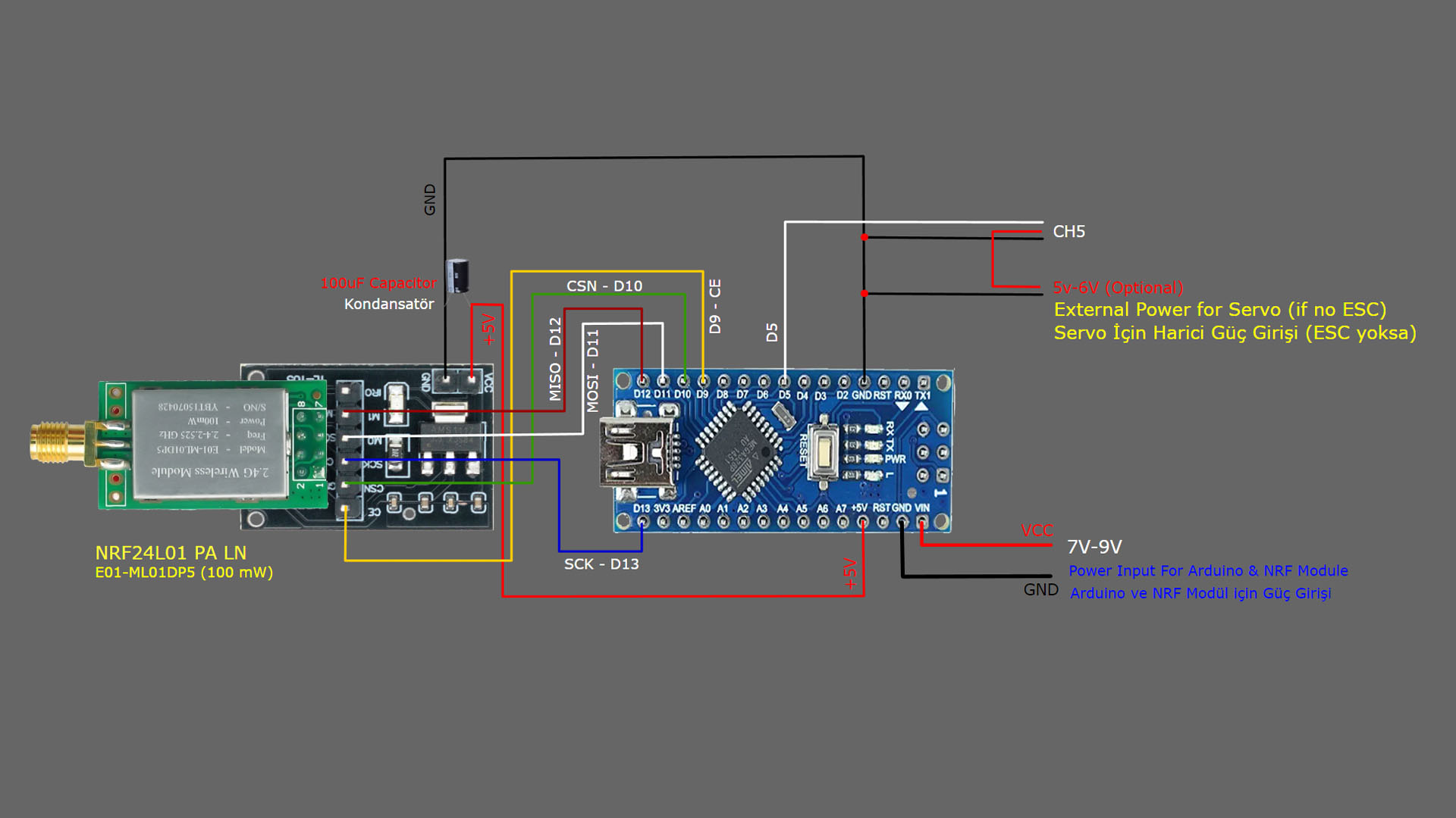
TRANSMITTER DIAGRAM:
TRANSMITTER CODE:
// 1 Channel Transmitter | 1 Kanal Verici
// Input pin A5

  #include <SPI.h>
  #include <nRF24L01.h>
  #include <RF24.h>
  const uint64_t pipeOut = 000322;    // NOTE: The same as in the receiver 000322 | Alıcı kodundaki adres ile aynı olmalı
  RF24 radio(9, 10);                          // select CE,CSN pin | CE ve CSN pinlerin seçimi

  struct Signal {
  byte aux1;
  byte aux3;

};
  Signal data;
  void ResetData()
{
  data.aux1 = 0;                       // Signal lost position | Sinyal kesildiğindeki pozisyon
  data.aux3 = 0;
}
  void setup()
{
                                       //Configure the NRF24 module  | NRF24 modül konfigürasyonu
  radio.begin();
  radio.openWritingPipe(pipeOut);
  radio.setChannel(100);
  radio.setAutoAck(false);
  radio.setDataRate(RF24_250KBPS);    // The lowest data rate value for more stable communication  | Daha kararlı iletişim için en düşük veri hızı.
  radio.setPALevel(RF24_PA_MAX);      // Output power is set for maximum |  Çıkış gücü maksimum için ayarlanıyor.
  radio.stopListening();              // Start the radio comunication for Transmitter | Verici için sinyal iletişimini başlatır.
  ResetData();

}
                                      // Joystick center and its borders | Joystick merkez ve sınırları
  int Border_Map(int val, int lower, int middle, int upper, bool reverse)
{
  val = constrain(val, lower, upper);
  if ( val < middle )
  val = map(val, lower, middle, 0, 128);
  else
  val = map(val, middle, upper, 128, 255);
  return ( reverse ? 255 - val : val );
}
  void loop()
{
                                     // Control Stick Calibration for channels  |  Her bir kanal için kumanda Kol Kalibrasyonları
  data.aux1 = Border_Map( analogRead(A5), 0, 512, 1023, true );   // "true" or "false" for change signal direction | "true" veya "false" sinyal yönünü değiştirir.

  data.aux3 = digitalRead(7);
  radio.write(&data, sizeof(Signal));
}
RECEIVER DIAGRAM:
RECEIVER CODE:
//  1 Channel Receiver | 1 Kanal Alıcı
//  PWM output on pin D5

#include <SPI.h>
#include <nRF24L01.h>
#include <RF24.h>
#include <Servo.h>

int ch_width_5 = 0;
int ch_width_7 = 0;

Servo ch5;
Servo ch7;

struct Signal {
byte aux1;
byte aux3;
};

Signal data;

const uint64_t pipeIn = 000322;
RF24 radio(9, 10);

void ResetData()
{

data.aux1 = 0;                                              // Define the inicial value of each data input. | Veri girişlerinin başlangıç değerleri
data.aux3 = 0;                                                            // The middle position for analog channels | Analog kanallar için orta konum
}

void setup()
{
                                                           // Set the pins for each PWM signal | Her bir PWM sinyal için pinler belirleniyor.

  ch5.attach(5);
  ch7.attach(7);

  ResetData();                                             // Configure the NRF24 module  | NRF24 Modül konfigürasyonu
  radio.begin();
  radio.openReadingPipe(1,pipeIn);
  radio.setChannel(100);
  radio.setAutoAck(false);
  radio.setDataRate(RF24_250KBPS);                          // The lowest data rate value for more stable communication  | Daha kararlı iletişim için en düşük veri hızı.
  radio.setPALevel(RF24_PA_MAX);                            // Output power is set for maximum |  Çıkış gücü maksimum için ayarlanıyor.
  radio.startListening();                                   // Start the radio comunication for receiver | Alıcı için sinyal iletişimini başlatır.

}

unsigned long lastRecvTime = 0;

void recvData()
{
while ( radio.available() ) {
radio.read(&data, sizeof(Signal));
lastRecvTime = millis();                                    // Receive the data | Data alınıyor
}
}

void loop()
{
recvData();
unsigned long now = millis();
if ( now - lastRecvTime > 1000 ) {
ResetData();                                                // Signal lost.. Reset data | Sinyal kayıpsa data resetleniyor
}

ch_width_5 = map(data.aux1, 0, 255, 1000, 2000);            // pin D5 (PWM signal)
ch_width_7 = map(data.aux3, 0, 1, 1000, 2000);
// ch_width_7 = map(data.aux3, 0, 1023, 0, 180);

ch5.writeMicroseconds(ch_width_5);                          // Write the PWM signal | PWM sinyaller çıkışlara gönderiliyor
ch7.writeMicroseconds(ch_width_7);

// ch7.write(ch_width_7);
}
Before uploading the codes to Arduino, you need to download the necessary library files to your computer. If there are no library files, the installation will not occur and an error will occur.
NRF24 Module Library File Links for download …..:
NRF24 Module library File (zip) : https://github.com/nRF24/RF24/archive/master.zip
NRF24 Module library Files (Github page): https://github.com/nRF24/RF24