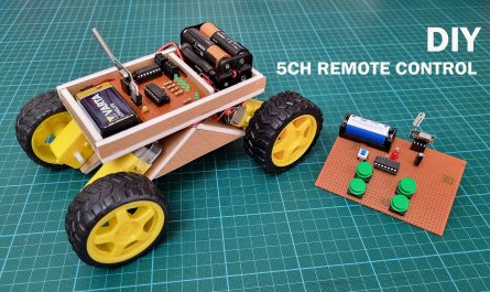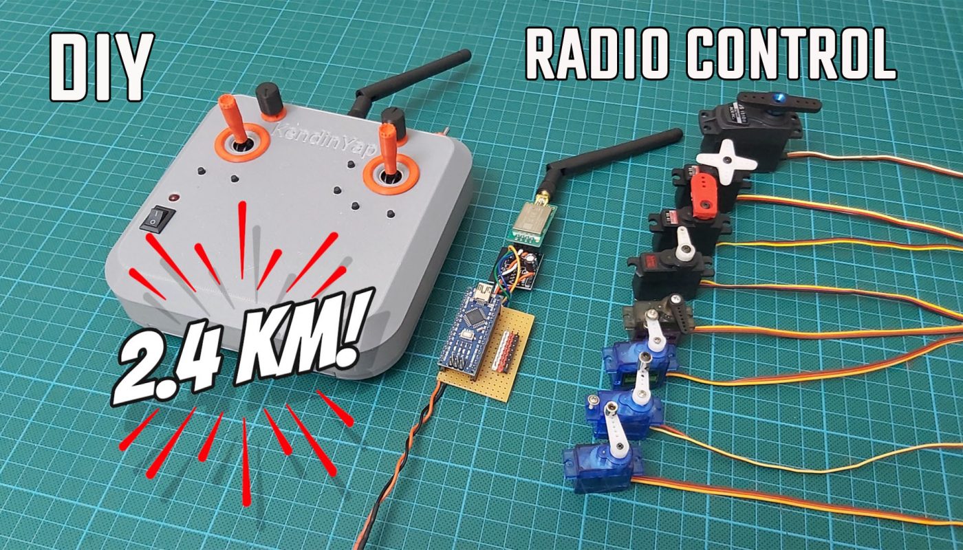
How to make long range remote control with 100mW NRF24L01 PA LN (E01-ML01DP5) 2.4Ghz module and Arduino.
It has 8 channels in total. 6 channels work proportionally. On the other hand, 2 channels are controlled by switch and work as on/off.
I also added digital trim for 3 channels to this remote control circuit. These trims work for Aileron (Roll), Elevator (Pitch) and Rudder (Yaw) channels.
In the first part of this RC circuit, I showed the basic setup with 1 channel active in “PART-1“. In PART-2, I added 7 more channels and completed it to 8 channels and added digital trims.
As I mentioned in PART-1, the biggest difference of these transmitter and receiver circuits from other Arduino remote control circuits is the E01-ML01DP5 modules I use. These modules are essentially the same as the NRF24L01 PA LN. But they are more powerful. When used as a transmitter, it can operate at 100mW (20dBm). Theoretically, it has a range of 2100 meters. When used as a receiver, it works at half power. In addition, thanks to its metal casing, it is less affected by electrical noise. In this way, it can work more stable.
I present some options for the construction of 8 channel remote control. Anyone who wants can make only 8 channels or 8 channels + trim. I also shared the option versions where the NRF24 module is fed directly from the arduino 5V pin or from the external power supply.
Necessary materials:
2 x PS4 Analogue Joystick : https://s.click.aliexpress.com/e/_DBSn2AB
2 x Toggle switch: https://s.click.aliexpress.com/e/_DCd5Pzh
2 x 100mW NRF24L01 PA LN (E01-ML01DP5): https://s.click.aliexpress.com/e/_DmEoWQf
2 x Arduino Nano: https://s.click.aliexpress.com/e/_DlhwLS3
2 x NRF24 wireless 3.3v adaptor: https://s.click.aliexpress.com/e/_DlmATh1
2 x 100uF electrolytic capacitors : https://s.click.aliexpress.com/e/_DBJpcn1
4 x Female Header Pin (15 pins): https://s.click.aliexpress.com/e/_DDqmgbh
2 x 10K potantiometer: https://s.click.aliexpress.com/e/_DCV1V11
Universal PCB board: https://s.click.aliexpress.com/e/_DF8xNJ9
AA Pil Kutusu (6xAA Cells) : https://s.click.aliexpress.com/e/_DFMnduf
veya 18650 pil kutusu : https://s.click.aliexpress.com/e/_DERuJnl
5mm LED: https://s.click.aliexpress.com/e/_DB6EXhh
330R Direnç: https://s.click.aliexpress.com/e/_DFkljF9
Rocker buton (10x15mm): https://s.click.aliexpress.com/e/_DDvMlXd
Tact buton (6x6x7): https://s.click.aliexpress.com/e/_Dm2yUBt
Screws: https://s.click.aliexpress.com/e/_DEvN4J9
26AWG cable: https://s.click.aliexpress.com/e/_DCRxV0z
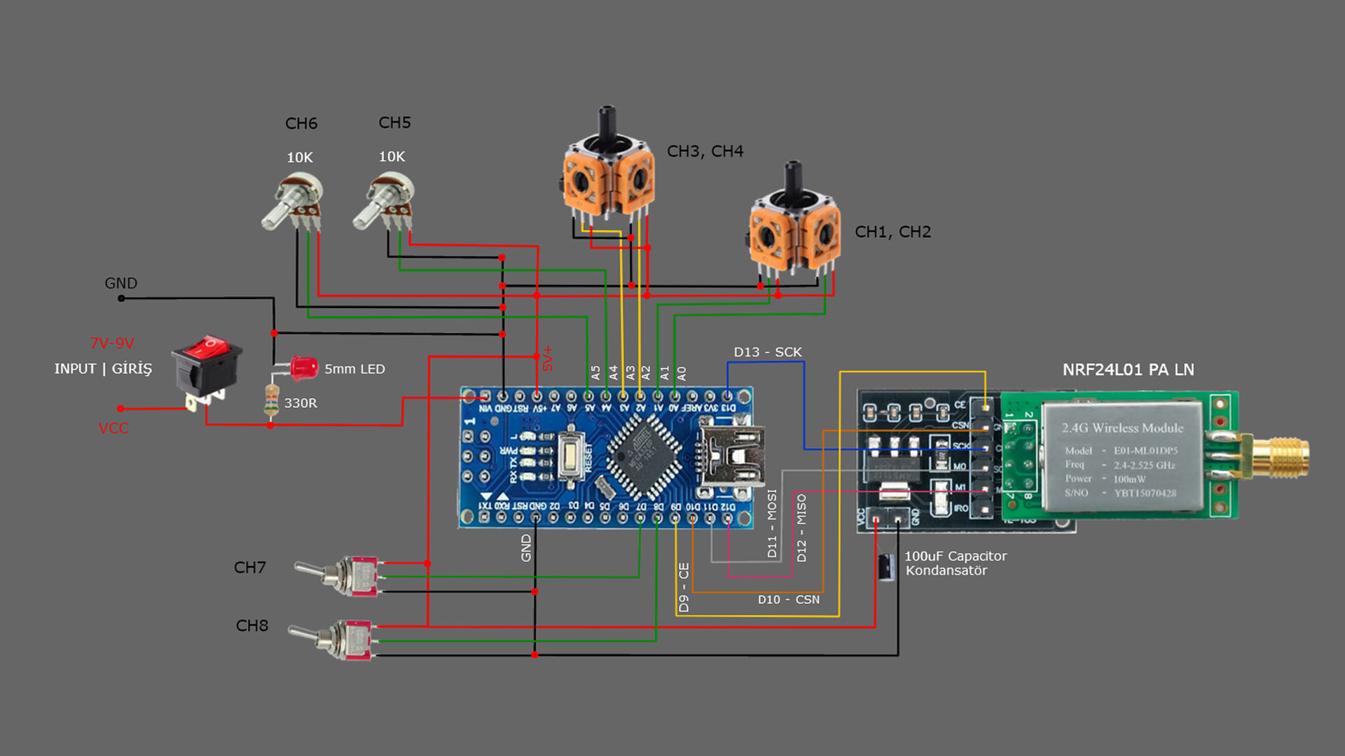
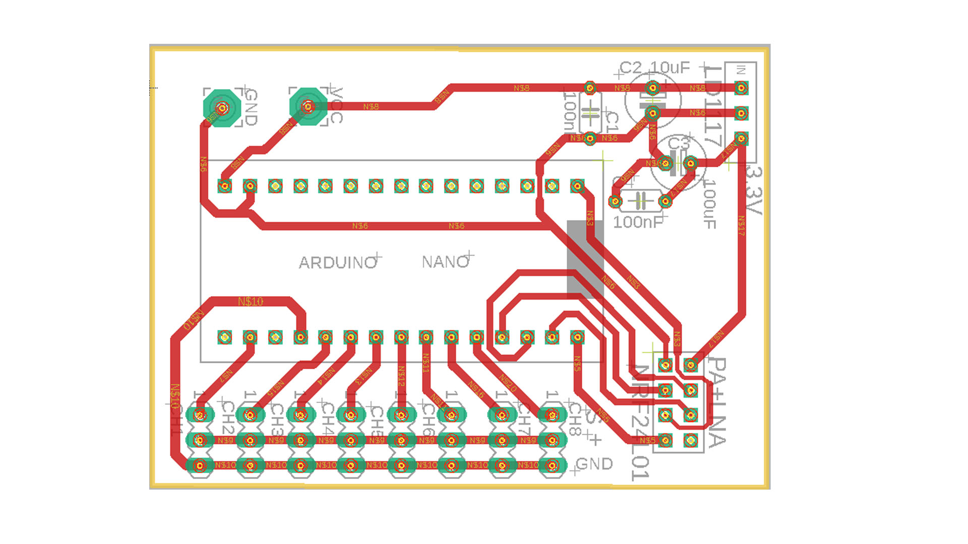
8 CHANNELS TRANSMITTER (TX) CIRCUIT :
8 CHANNELS TRANSMITTER (TX) CODE (No Trim):
// 8 Channel Transmitter (No Trim) | 8 Kanal Verici (Trim Yok)
// Input pin A5

  #include <SPI.h>
  #include <nRF24L01.h>
  #include <RF24.h>
  const uint64_t pipeOut = 000322;         // NOTE: The same as in the receiver 000322 | Alıcı kodundaki adres ile aynı olmalı
  RF24 radio(9, 10);                       // select CE,CSN pin | CE ve CSN pinlerin seçimi

  struct Signal {
  byte throttle;
  byte pitch;
  byte roll;
  byte yaw;
  byte aux1;
  byte aux2;
  byte aux3;
  byte aux4;

};
  Signal data;
  void ResetData()
{
  data.throttle = 0;
  data.pitch = 127;
  data.roll = 127;
  data.yaw = 127;
  data.aux1 = 0;                       // Signal lost position | Sinyal kesildiğindeki pozisyon
  data.aux2 = 0;
  data.aux3 = 0;
  data.aux4 = 0;
}
  void setup()
{
                                       //Configure the NRF24 module  | NRF24 modül konfigürasyonu
  radio.begin();
  radio.openWritingPipe(pipeOut);
  radio.setChannel(100);
  radio.setAutoAck(false);
  radio.setDataRate(RF24_250KBPS);    // The lowest data rate value for more stable communication  | Daha kararlı iletişim için en düşük veri hızı.
  radio.setPALevel(RF24_PA_MAX);      // Output power is set for maximum |  Çıkış gücü maksimum için ayarlanıyor.
  radio.stopListening();              // Start the radio comunication for Transmitter | Verici için sinyal iletişimini başlatır.
  ResetData();

}
                                      // Joystick center and its borders | Joystick merkez ve sınırları
  int Border_Map(int val, int lower, int middle, int upper, bool reverse)
{
  val = constrain(val, lower, upper);
  if ( val < middle )
  val = map(val, lower, middle, 0, 128);
  else
  val = map(val, middle, upper, 128, 255);
  return ( reverse ? 255 - val : val );
}
  void loop()
{
                                     // Control Stick Calibration for channels  |  Her bir kanal için kumanda Kol Kalibrasyonları

  data.roll = Border_Map( analogRead(A3), 0, 512, 1023, true );        // "true" or "false" for signal direction | "true" veya "false" sinyal yönünü belirler
  data.pitch = Border_Map( analogRead(A2), 0, 512, 1023, true );
  data.throttle = Border_Map( analogRead(A1),570, 800, 1023, false );  // For Single side ESC | Tek yönlü ESC için
  // data.throttle = Border_Map( analogRead(A1),0, 512, 1023, false ); // For Bidirectional ESC | Çift yönlü ESC için
  data.yaw = Border_Map( analogRead(A0), 0, 512, 1023, true );
  data.aux1 = Border_Map( analogRead(A4), 0, 512, 1023, true );        // "true" or "false" for change signal direction | "true" veya "false" sinyal yönünü değiştirir.
  data.aux2 = Border_Map( analogRead(A5), 0, 512, 1023, true );        // "true" or "false" for change signal direction | "true" veya "false" sinyal yönünü değiştirir.
  data.aux3 = digitalRead(7);
  data.aux4 = digitalRead(8);

  radio.write(&data, sizeof(Signal));
}
NOTE: The words “true” and “false” determine the direction of the servo. If we write “false” instead of “true”, the signal direction will change and the servo will move to the other side. So the “reverse” command works.
CIRCUIT FOR 8 CHANNELS TRANSMITTER WITH TRIM:
CODE FOR 8 CHANNELS TRANSMITTER WITH TRIM:
// 8 Channel Transmitter & Trims | 8 Kanal Verici ve Trimler

  #include <SPI.h>
  #include <nRF24L01.h>
  #include <RF24.h>
  #include <EEPROM.h>

  const uint64_t pipeOut = 000322;        // NOTE: The same as in the receiver 000322 | Alıcı kodundaki adres ile aynı olmalı
  RF24 radio(9, 10);                      // Select CE,CSN pin | CE ve CSN pinlerin seçimi

 #define trimbut_1 1                      // Trim button 1 / Pin D1
 #define trimbut_2 2                      // Trim button 2 / Pin D2
 #define trimbut_3 3                      // Trim button 3 / Pin D3
 #define trimbut_4 4                      // Trim button 4 / Pin D4
 #define trimbut_5 5                      // Trim button 5 / Pin D5
 #define trimbut_6 6                      // Trim button 6 / Pin D6

 int tvalue1 = EEPROM.read(1) * 4;        // Reading trim values from Eprom  |  Trim değerlerinin Epromdan okunması
 int tvalue2 = EEPROM.read(3) * 4;
 int tvalue3 = EEPROM.read(5) * 4;

  struct Signal {
  byte throttle;
  byte pitch;
  byte roll;
  byte yaw;
  byte aux1;
  byte aux2;
  byte aux3;
  byte aux4;
};

  Signal data;
  void ResetData()
{
  data.throttle = 512;                      // Signal lost position | Sinyal kesildiğindeki pozisyon
  data.pitch = 127;
  data.roll = 127;
  data.yaw = 127;
  data.aux1 = 0;
  data.aux2 = 0;
  data.aux3 = 0;
  data.aux4 = 0;
}
  void setup()
{
                                         // Configure the NRF24 module  | NRF24 modül konfigürasyonu
  radio.begin();
  radio.openWritingPipe(pipeOut);
  radio.setChannel(100);
  radio.setAutoAck(false);
  radio.setDataRate(RF24_250KBPS);       // The lowest data rate value for more stable communication  | Daha kararlı iletişim için en düşük veri hızı.
  radio.setPALevel(RF24_PA_MAX);         // Output power is set for maximum |  Çıkış gücü maksimum için ayarlanıyor.
  radio.stopListening();                 // Start the radio comunication for Transmitter | Verici için sinyal iletişimini başlatır.
  ResetData();

  pinMode(trimbut_1, INPUT_PULLUP);
  pinMode(trimbut_2, INPUT_PULLUP);
  pinMode(trimbut_3, INPUT_PULLUP);
  pinMode(trimbut_4, INPUT_PULLUP);
  pinMode(trimbut_5, INPUT_PULLUP);
  pinMode(trimbut_6, INPUT_PULLUP);

  tvalue1= EEPROM.read(1) * 4;
  tvalue2= EEPROM.read(3) * 4;
  tvalue3= EEPROM.read(5) * 4;
}

// Joystick center and its borders | Joystick merkez ve sınırları
  int Border_Map(int val, int lower, int middle, int upper, bool reverse)
{
  val = constrain(val, lower, upper);
  if ( val < middle )
  val = map(val, lower, middle, 0, 128);
  else
  val = map(val, middle, upper, 128, 255);
  return ( reverse ? 255 - val : val );
}
  void loop()
{

// Trims and Limiting trim values  |  Trimler ve Trim değerlerini sınırlandırma

  if(digitalRead(trimbut_1)==LOW and tvalue1 < 630) {
    tvalue1=tvalue1+15;
    EEPROM.write(1,tvalue1/4);
    delay (130);
  }
  if(digitalRead(trimbut_2)==LOW and tvalue1 > 280){
    tvalue1=tvalue1-15;
    EEPROM.write(1,tvalue1/4);
    delay (130);
  }

  if(digitalRead(trimbut_3)==LOW and tvalue2 < 630) {
    tvalue2=tvalue2+15;
    EEPROM.write(3,tvalue2/4);
    delay (130);
  }
  if(digitalRead(trimbut_4)==LOW and tvalue2 > 280){
    tvalue2=tvalue2-15;
    EEPROM.write(3,tvalue2/4);
    delay (130);
  }

    if(digitalRead(trimbut_5)==LOW and tvalue3 < 630) {
     tvalue3=tvalue3+15;
     EEPROM.write(5,tvalue3/4);
     delay (130);
  }
  if(digitalRead(trimbut_6)==LOW and tvalue3 > 280){
    tvalue3=tvalue3-15;
    EEPROM.write(5,tvalue3/4);
    delay (130);
  }

// Control Stick Calibration for channels  |  Her bir kanal için kumanda Kol Kalibrasyonları

  data.roll = Border_Map( analogRead(A3), 0, tvalue1, 1023, true );       // "true" or "false" for signal direction | "true" veya "false" sinyal yönünü belirler
  data.pitch = Border_Map( analogRead(A2), 0, tvalue2, 1023, true );
  data.throttle = Border_Map( analogRead(A1),570, 800, 1023, false );    // For Single side ESC | Tek yönlü ESC için
  // data.throttle = Border_Map( analogRead(A1),0, 512, 1023, false );   // For Bidirectional ESC | Çift yönlü ESC için
  data.yaw = Border_Map( analogRead(A0), 0, tvalue3, 1023, true );
  data.aux1 = Border_Map( analogRead(A4), 0, 512, 1023, true );
  data.aux2 = Border_Map( analogRead(A5), 0, 512, 1023, true );
  data.aux3 = digitalRead(7);
  data.aux4 = digitalRead(8);
  radio.write(&data, sizeof(Signal));
}
Note:
– Since the PS4 joysticks I use for throttle control are spring loaded, they return to the center when I release the lever. This situation is not suitable for one-way ESCs. Therefore, the arm controlling the throttle channel (3rd channel) should be adjusted as if it is at the minimum position when it is in the center. The first two values “570, 800” in the “data.throttle” line provide this. For bidirectional ESCs (such as car and boat esc), values of “0, 512” are used as in other channels.
– In the roll, pitch and yaw lines, the first value is the variable named “tvalue”. This variable stores the values from the trim control buttons. This value changes the center position of the channel.
Trim values are saved in the eprom.
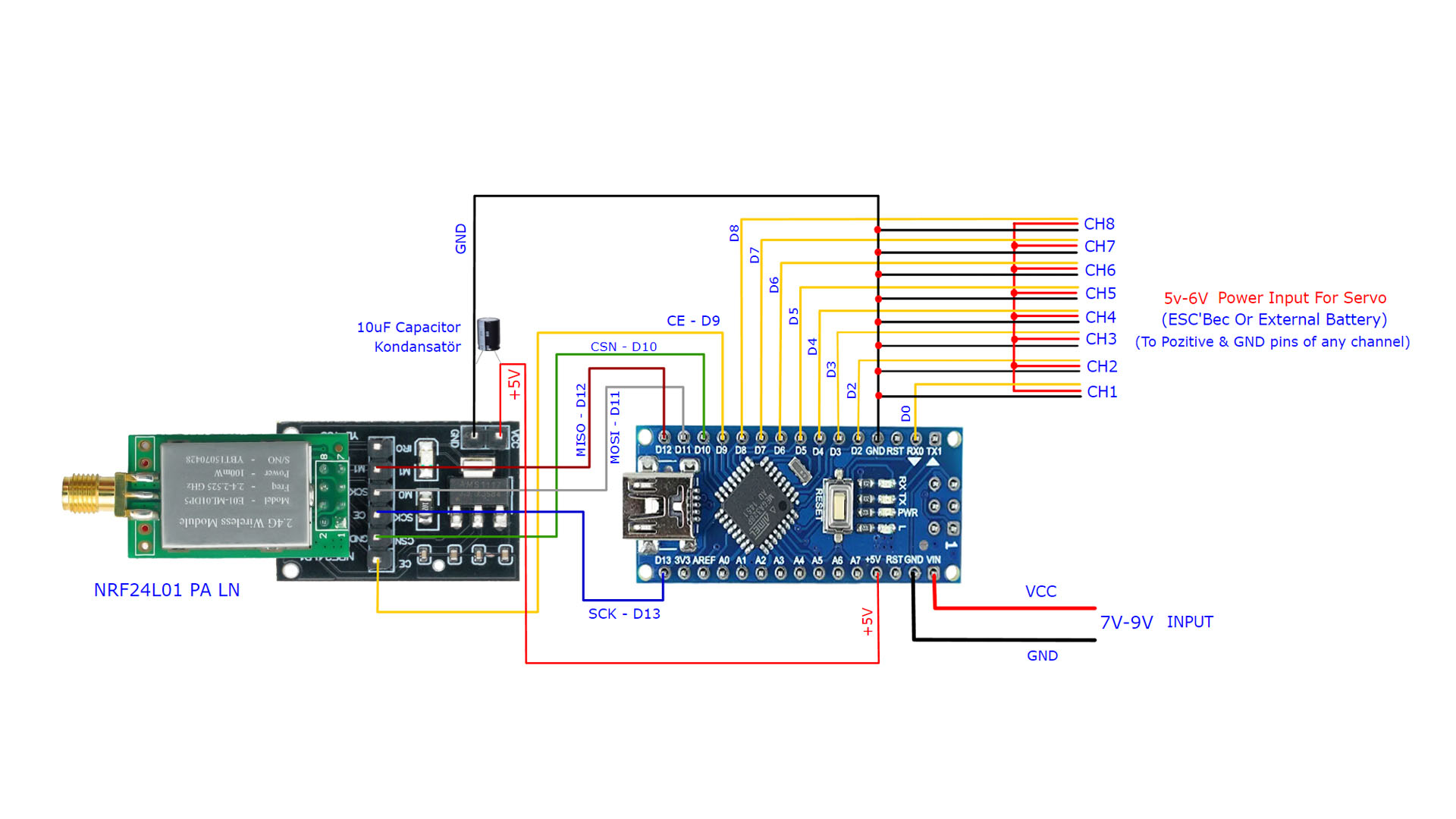
8 CHANNELS RECEIVER (RX) CIRCUT:
8 CHANNEL RECEVIER (RX) CODE:
//  8 Channel Receiver | 8 Kanal Alıcı

#include <SPI.h>
#include <nRF24L01.h>
#include <RF24.h>
#include <Servo.h>

int ch_width_1 = 0;
int ch_width_2 = 0;
int ch_width_3 = 0;
int ch_width_4 = 0;
int ch_width_5 = 0;
int ch_width_6 = 0;
int ch_width_7 = 0;
int ch_width_8 = 0;

Servo ch1;
Servo ch2;
Servo ch3;
Servo ch4;
Servo ch5;
Servo ch6;
Servo ch7;
Servo ch8;

struct Signal {

byte throttle;
byte pitch;
byte roll;
byte yaw;
byte aux1;
byte aux2;
byte aux3;
byte aux4;
};

Signal data;

const uint64_t pipeIn = 000322;
RF24 radio(9, 10);

void ResetData()
{

data.throttle = 0;
data.roll = 127;
data.pitch = 127;
data.yaw = 127;
data.aux1 = 0;                                              // Define the inicial value of each data input. | Veri girişlerinin başlangıç değerleri
data.aux2 = 0;
data.aux3 = 0;
data.aux4 = 0;
}

void setup()
{
                                                           // Set the pins for each PWM signal | Her bir PWM sinyal için pinler belirleniyor.
  ch1.attach(0);
  ch2.attach(2);
  ch3.attach(3);
  ch4.attach(4);
  ch5.attach(5);
  ch6.attach(6);
  ch7.attach(7);
  ch8.attach(8);

  ResetData();                                             // Configure the NRF24 module  | NRF24 Modül konfigürasyonu
  radio.begin();
  radio.openReadingPipe(1,pipeIn);
  radio.setChannel(100);
  radio.setAutoAck(false);
  radio.setDataRate(RF24_250KBPS);                          // The lowest data rate value for more stable communication  | Daha kararlı iletişim için en düşük veri hızı.
  radio.setPALevel(RF24_PA_MAX);                            // Output power is set for maximum |  Çıkış gücü maksimum için ayarlanıyor.
  radio.startListening();                                   // Start the radio comunication for receiver | Alıcı için sinyal iletişimini başlatır.

}

unsigned long lastRecvTime = 0;

void recvData()
{
while ( radio.available() ) {
radio.read(&data, sizeof(Signal));
lastRecvTime = millis();                                    // Receive the data | Data alınıyor
}
}

void loop()
{
recvData();
unsigned long now = millis();
if ( now - lastRecvTime > 1000 ) {
ResetData();                                                // Signal lost.. Reset data | Sinyal kayıpsa data resetleniyor
}

ch_width_1 = map(data.roll, 0, 255, 1000, 2000);
ch_width_2 = map(data.pitch, 0, 255, 1000, 2000);
ch_width_3 = map(data.throttle, 0, 255, 1000, 2000);
ch_width_4 = map(data.yaw, 0, 255, 1000, 2000);
ch_width_5 = map(data.aux1, 0, 255, 1000, 2000);
ch_width_6 = map(data.aux2, 0, 255, 1000, 2000);
ch_width_7 = map(data.aux3, 0, 1, 1000, 2000);
ch_width_8 = map(data.aux4, 0, 1, 1000, 2000);


ch1.writeMicroseconds(ch_width_1);                          // Write the PWM signal | PWM sinyaller çıkışlara gönderiliyor
ch2.writeMicroseconds(ch_width_2);
ch3.writeMicroseconds(ch_width_3);
ch4.writeMicroseconds(ch_width_4);
ch5.writeMicroseconds(ch_width_5);
ch6.writeMicroseconds(ch_width_6);
ch7.writeMicroseconds(ch_width_7);
ch8.writeMicroseconds(ch_width_8);


}
NOTE: The values “1000” and “2000” in the map command of the receiver code determine the maximum movement limits of the servo. With 1000 and 2000 values, 120° servo movement is obtained. For example, if you change these values to 800 and 2300, the servo can move 180° in total. You can change these values according to your needs. (Min 800, can be max 2300)
OPTIONAL ADDITIONS:
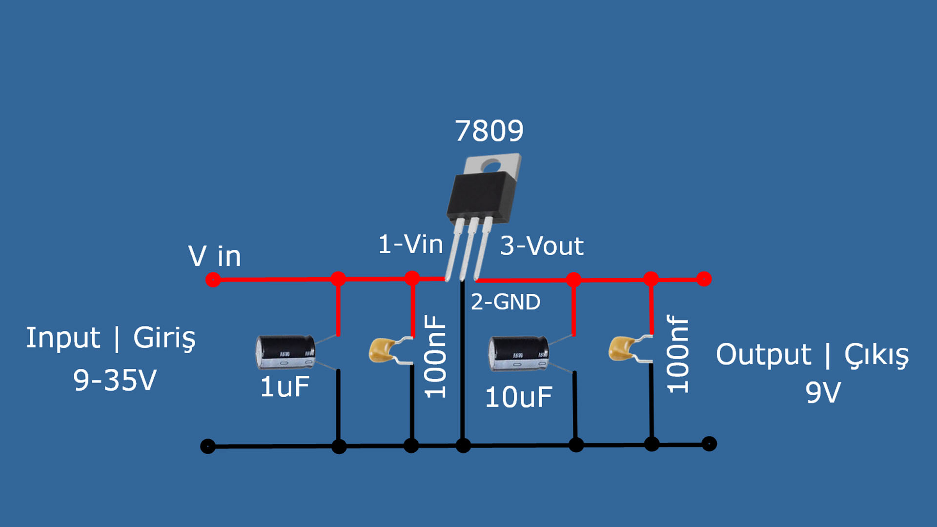
If you want to use the receiver circuit with 3S – 6S LiPo, it will be necessary to add a voltage reducer (Regulator) circuit. Because Arduino nano can work directly with a maximum of 10V.
Below is a diagram showing the 9V voltage regulator circuit and its attached to the receiver circuit.
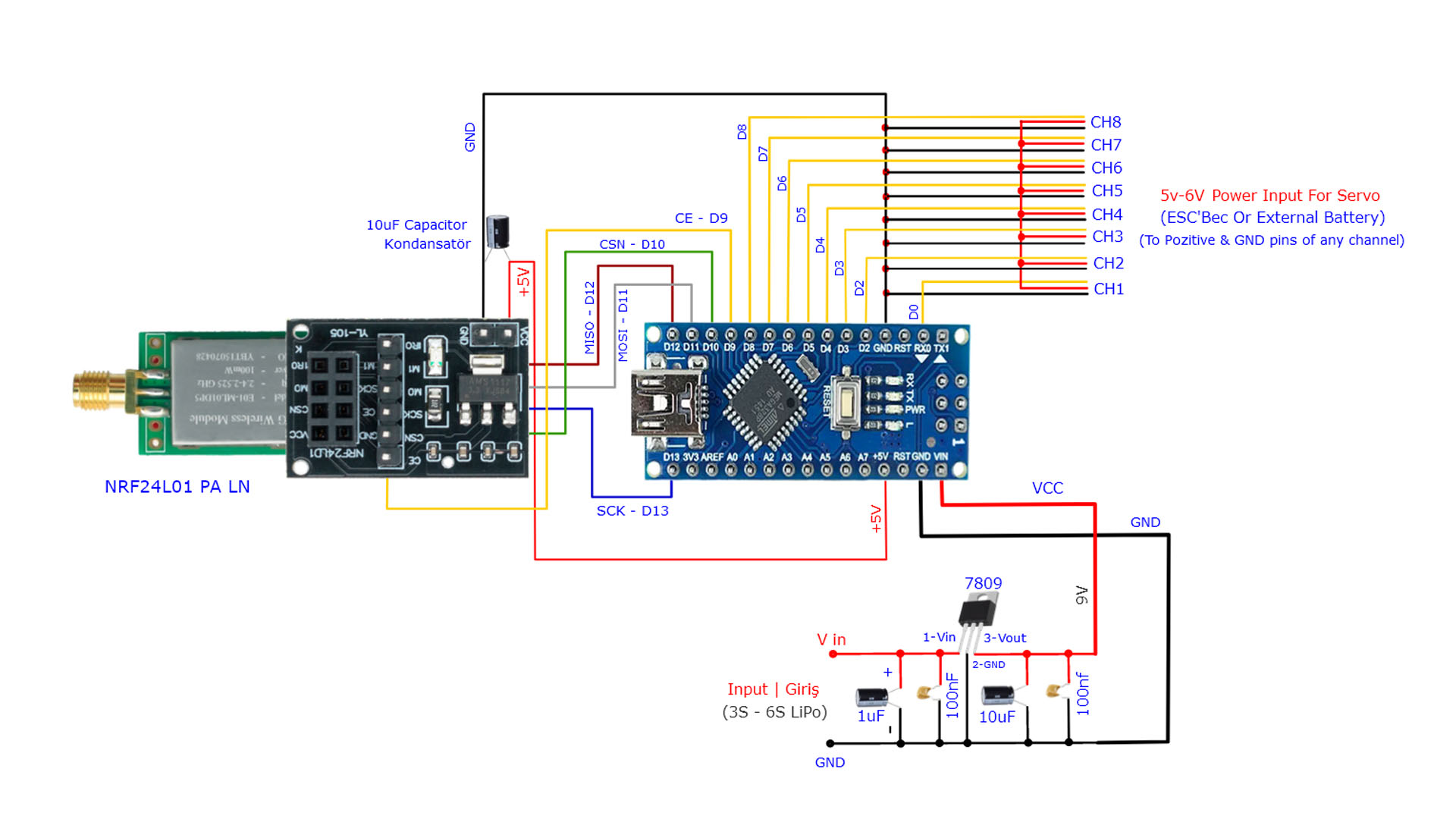
NOTE: The maximum continuous current support for the 5V pin of the Arduino is 20mA (Momentary 40mA). The NRF module, on the other hand, draws about 12.32 mA as I showed in the video. That’s why I didn’t add an external power supply. But when I searched the technical specifications for the E01-ML01DP5 NRF24 module, it was given a maximum of 20mA when used as a receiver, and a maximum of 130mA when used as a transmitter. But I could not find the official manufacturer site or a datasheet showing the technical specifications for this version of NRF24. Therefore, I took into account the current value I measured myself and did not use an external power supply.
For those who still prefer an external power supply, I have shared the relevant circuit diagrams below.
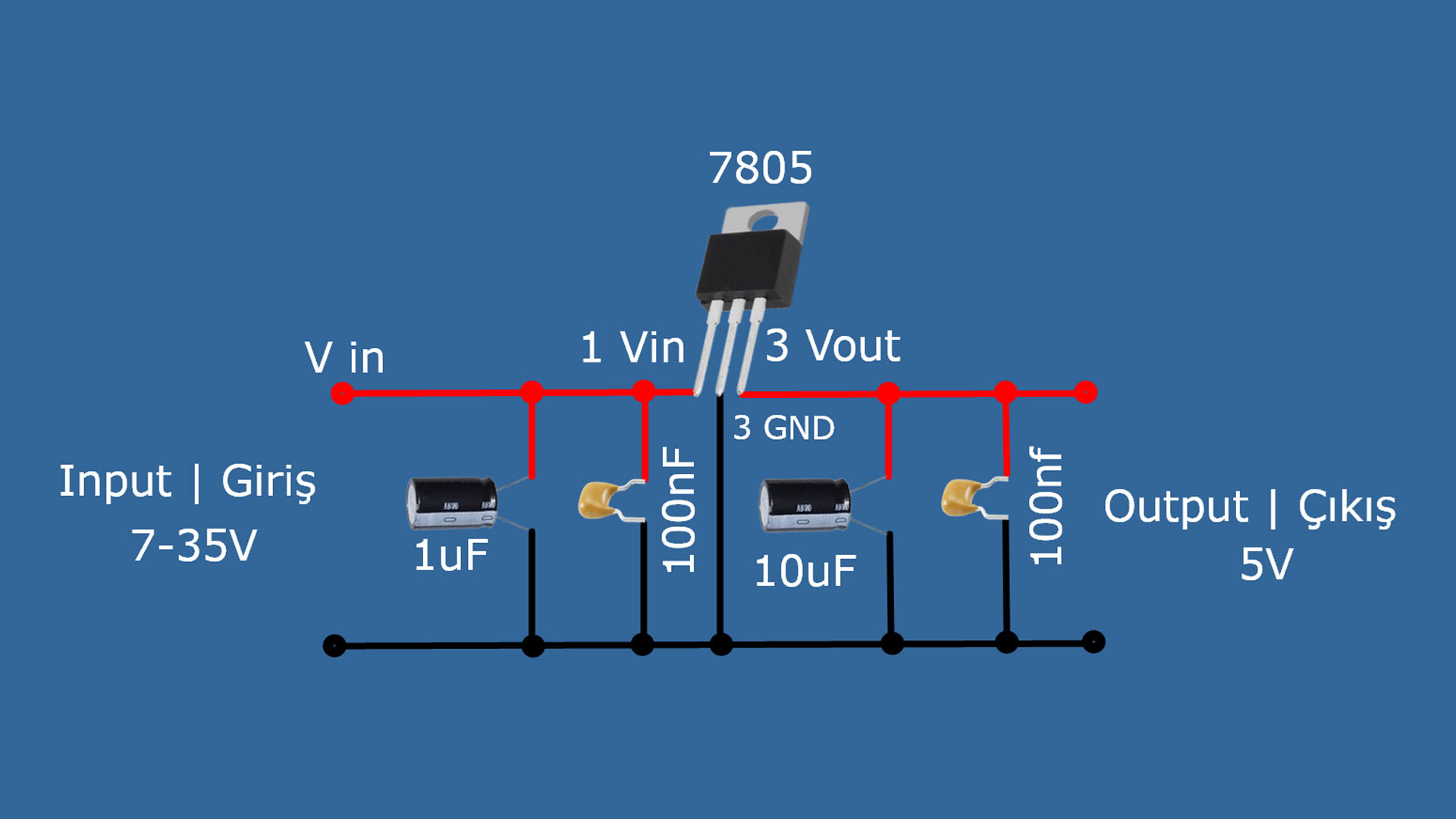
Step-down regulator circuit and transmitter circuit diagram for 5V (Optional):
Required materials for regulators:
1uF electrolytic capacitors : https://s.click.aliexpress.com/e/_DDVm071
10uF electrolytic capacitors: https://s.click.aliexpress.com/e/_Ddfia2R
100nF ceramic capacitor: https://s.click.aliexpress.com/e/_Dd496aB
7805 5V Regulator IC: https://s.click.aliexpress.com/e/_DDvYt5v
7809 9V Regulator IC: https://s.click.aliexpress.com/e/_DlXmEG7
80W soldering iron: https://s.click.aliexpress.com/e/_DD75tWX
Digital Multimetre AC DC A830L : https://s.click.aliexpress.com/e/_DmjzgOJ
Profesyonel Digital Multimetre Tester: https://s.click.aliexpress.com/e/_DmtkrmJ
OPTIONAL PDF & GERBER FILES FOR 8CH RECEIVER ______________________ :
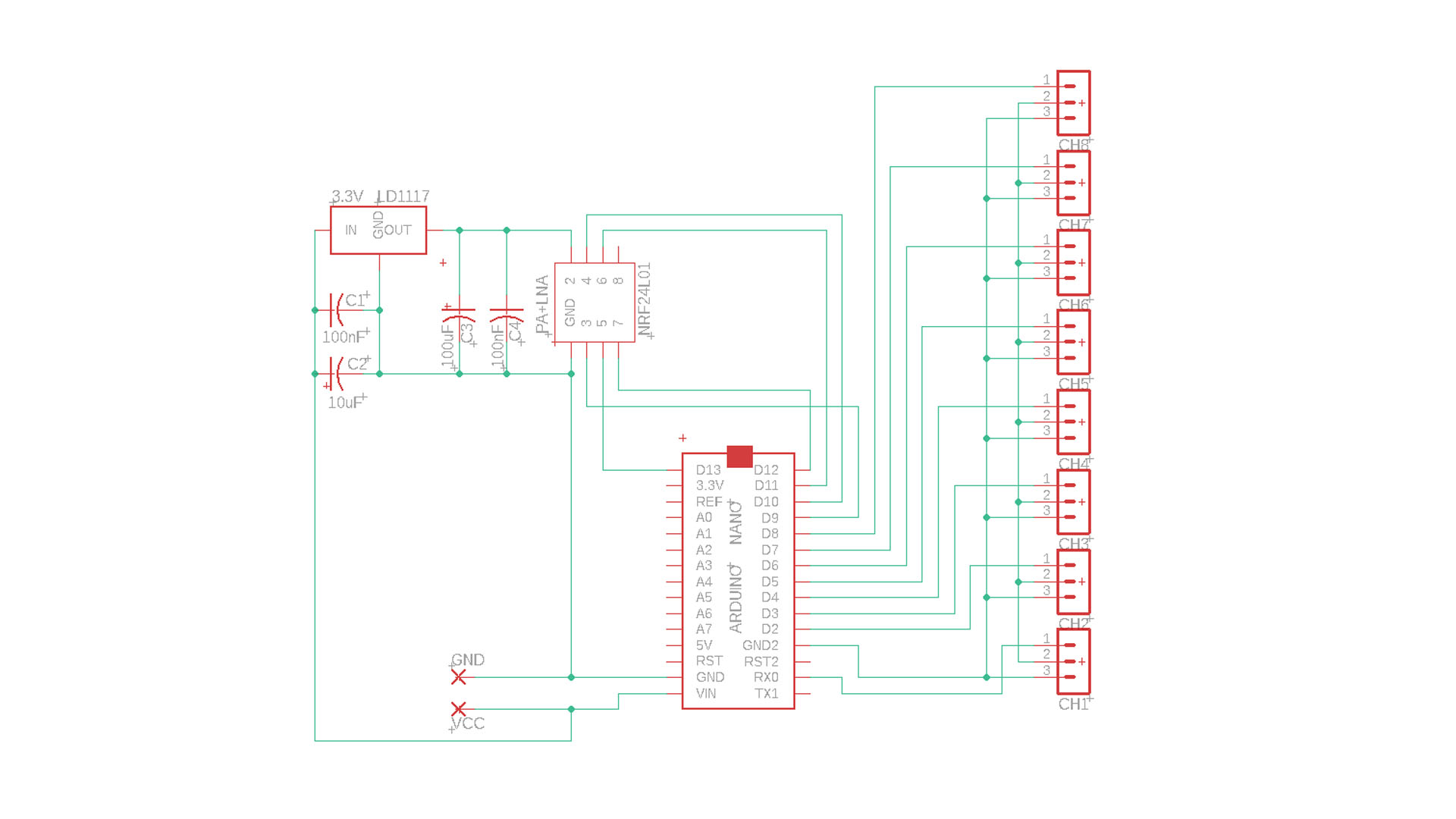
8CH Receiver PDF & Gerber Files Download Link: https://drive.google.com/file/d/1p0soy_jqxCMs4R-HkBWkn96yaJsdM7ct/view?usp=sharing
NOTE: An external NRF24 wireless adapter is not required for this version. It is embedded on the circuit.
Radio Box 3D STL Files: https://drive.google.com/file/d/1DkdLwerpLfWJpYLvgysXO7k6Kb_76Z4K/view?usp=sharing